8.9
Date Code 20171006 Instruction Manual SEL-400 Series Relays
Monitoring
Circuit Breaker Monitor
Circuit Breaker Monitor Close Initiation Settings: BM1CLS
NOTE: In the following discussion,
three elements are specified. There is
one element for each phase: = A, B,
and C. With three-pole breakers, only
phase A is used to represent the
entire breaker. Some three-pole relays
include A in the names and others
drop it.
The relay employs SELOGIC control equations to initiate the circuit breaker mon-
itor duration timers for close functions. For Circuit Breaker 1, this setting is
BM1CLS. These SEL
OGIC control equations use Relay Word bits to determine
when the circuit breaker monitor times mechanical closing, electrical closing,
and pole scatter. Table 8.5 shows the factory-default settings for circuit breaker
monitor close initiation.
As in Example 8.4 (connection of the trip bus to a control input), you can also
capture the circuit breaker close information by using a relay input to monitor the
close bus for the given circuit breaker.
Other Circuit Breaker Monitor Functions
kA Interrupt Monitoring
The relay monitors the amount of phase current that each pole of the circuit
breaker interrupts at each trip operation. The relay records the interrupted current
as a percentage of the circuit breaker maximum interrupting rating specified by
the manufacturer. Set the maximum interruption current with setting B1MKAI
(Maximum kA Interrupt Rating—BK1). If the percent of current interrupt that
the relay records exceeds threshold setting B1KAIAT (kA Interrupt Capacity
Alarm Threshold—BK1), the relay asserts breaker monitor alarm Relay Word bit
B1KAIAL.
Mechanical Operating Time
The mechanical operating time is the time between trip initiation or close initia-
tion and the associated phase circuit breaker 52A normally open contact status
change. (Assertion of 52A1 indicates that a particular circuit breaker phase has
closed). The relay measures the tripping times for each phase from the assertion
of the respective BM1TRPRelay Word bit to the dropout of the respective
52A1 Relay Word bit. Similarly, for mechanical closing time, the relay mea-
sures the closing times for each phase from the assertion of the BM1CLS Relay
Word bit to the pickup of the 52A1 Relay Word bit. The relay compares these
tripping or closing times to the mechanical slow operation time thresholds for
tripping and closing, B1MSTRT and B1MSCLT, respectively. The relay issues a
mechanical slow operation alarm, B1MSOAL, for 5 seconds when trip or close
times exceed these thresholds. See Figure 8.5 for a Circuit Breaker 1 A-Phase
timing diagram.
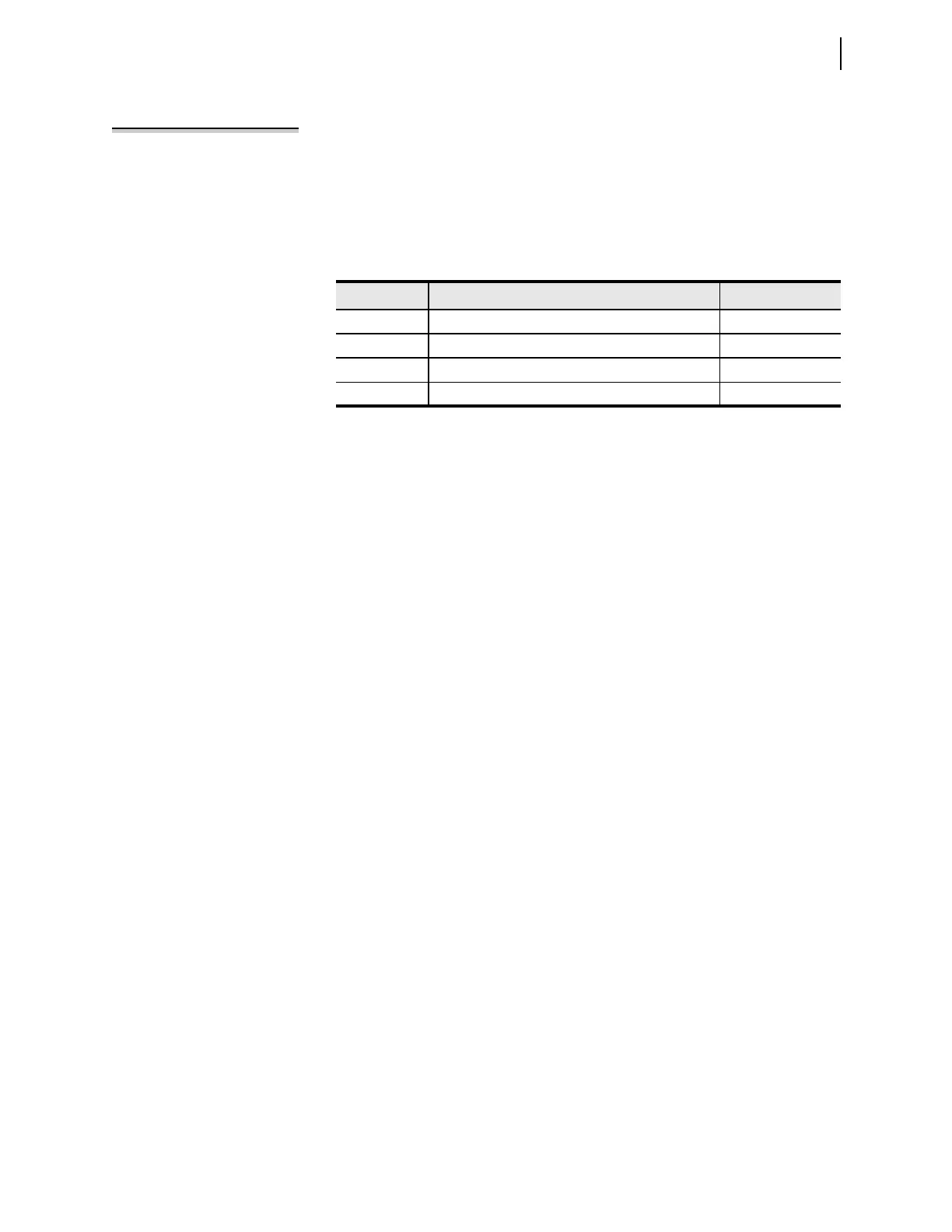
Table 8.5 Circuit Breaker Monitor Close SELOGIC Control Equations
Name Description Comment
a
a
See
Ta bl e 8 .1
.
BM1CLSA Breaker Monitor 1 close equation If BK1TYP := 3
BM1CLSA Breaker Monitor 1 A-Phase close equation If BK1TYP := 1
BM1CLSB Breaker Monitor 1 B-Phase close equation If BK1TYP := 1
BM1CLSC Breaker Monitor 1 C-Phase close equation If BK1TYP := 1