10.9
Date Code 20171006 Instruction Manual SEL-400 Series Relays
Testing, Troubleshooting, and Maintenance
Test Methods
e. The relay checks the validity of the setting you entered.
An invalid setting (you could have mistyped the element name)
causes the OUT105 text box to turn red.
If the setting is valid, the text box displays the new setting on a
white background.
Step 4. Click File > Save to save the new settings in QuickSet.
Step 5. Upload the new settings to the SEL-451.
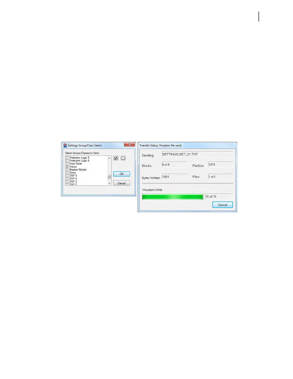
a. Click File > Send.
QuickSet prompts you for the settings class you want to send to
the relay, as shown in the Group Select dialog box in Figure 10.3.
b. Click the Output check box.
c. Click OK.
The relay responds with the Transfer Status dialog box, as
shown in Figure 10.3.
If you see no error message, the new settings are loaded in the relay.
Step 6. Connect an indicating device to OUT105 on the relay rear panel.
A VOM multi-tester on a low resistance scale can indicate an
OUT105 control output closure.
Step 7. Connect a test source to the relay.
a. Set the current output of a test source to zero output level.
b. Connect a single-phase current output of the test source to the
IAW analog input.
Step 8. Increase the current source to produce a current magnitude greater
than 15.00 A secondary in the relay (to test the element).
When the 50P1 element picks up, the relay changes the 50P1 Relay
Word bit to logical 1 and closes the output contacts of control output
OUT105.
The indicating device operates.
Figure 10.3 Uploading Output Settings to the SEL-451