12.5
Date Code 20171006 Instruction Manual SEL-400 Series Relays
Settings
Multiple Setting Groups
For example, if setting Group 4 is the active setting group, Relay Word bit SG4
asserts to logical 1, and the other Relay Word bits SG1, SG2, SG3, SG5, and SG6
are all deasserted to logical 0.
Active Setting Group Selection
The Global settings class contains the SELOGIC control equation settings SS1
through SS6, as shown in Table 12.3.
NOTE: The settings group switching
settings are checked once per cycle.
When setting TGR := 0, in order for a
transient assertion to be recognized,
it should be conditioned to remain
asserted for at least 1 cycle.
The operation of these settings is explained with the following example.
Assume the active setting group starts out as setting Group 3. Corresponding
Relay Word bit SG3 is asserted to logical 1 as an indication that setting Group 3
is the active setting group.
With setting Group 3 as the active setting group, setting SS3 has priority. If set-
ting SS3 is asserted to logical 1, setting Group 3 remains the active setting group,
regardless of the activity of settings SS1, SS2, SS4, SS5, and SS6. With settings
SS1 through SS6 all deasserted to logical 0, setting Group 3 still remains the
active setting group.
With setting Group 3 as the active setting group, if setting SS3 is deasserted to
logical 0 and one of the other settings (e.g., setting SS5) asserts to logical 1, the
relay switches from setting Group 3 as the active setting group to another setting
group (e.g., setting Group 5) as the active setting group, after qualifying time set-
ting TGR (Global settings):
NOTE: The CHSG Relay Word bit
does not operate for settings changes
initiated by the serial port or front
panel methods.
In this example, TGR qualifies the assertion of setting SS5 before it can change
the active setting group. Relay Word bit CHSG asserts when the TGR timer is
picked-up and timing, and also when a setting group change has been initiated.
Active Setting Group Changes
The relay is disabled for less than one second while in the process of changing
active setting groups. Relay elements, timers, and logic are reset, unless indicated
otherwise in the specific logic description. For example, local bit (LB01 through
LB32), remote bit (RB01 through RB32), and latch bit (PLT01 through PLT32)
states are retained during an active setting group change. The output contacts do
not change state until the relay enables in the new settings group and the
SEL
OGIC control equations are processed to determine the output contact status
for the new group.
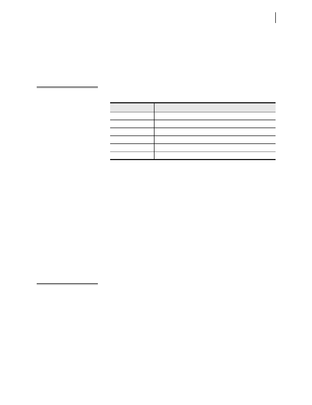
Table 12.3 Definitions for Active Setting Group Switching SELOGIC Control
Equation Settings SS1 Through SS6
Setting Definition
SS1 Go to (or remain in) setting Group 1
SS2 Go to (or remain in) setting Group 2
SS3 Go to (or remain in) setting Group 3
SS4 Go to (or remain in) setting Group 4
SS5 Go to (or remain in) setting Group 5
SS6 Go to (or remain in) setting Group 6
TGR Group Change
Delay Setting
(settable from 0 to 54000 cycles)