13.9
Date Code 20171006 Instruction Manual SEL-400 Series Relays
SELOGIC Control Equation Programming
SEL
OGIC Control Equation Elements
SELOGIC Control Equation Elements
SELOGIC control equation elements are a collection of storage locations, timers,
and counters that you can use to customize the operation of your relay and to
automate substation operation. The elements that you can use in SEL
OGIC control
equations are summarized in Table 13.1. The specific number of the various types
of elements varies between SEL-400 series relays. See the product-specific
instruction manual to determine the number of each type of element in that relay.
Relay Word Bits and Analog Quantities
Data within the relay are available for use in SELOGIC control equations. Relay
Word bits are binary data that include protection elements, input status, and out-
put status. See Section 11: Relay Word Bits in each product-specific instruction
manual to view a list of Relay Word bits available within that relay. Analog quan-
tities are analog values within the relay including measured and calculated val-
ues. Section 12: Analog Quantities in each product-specific instruction manual
contains a list of analog quantities available within the relay.
Special Condition Bits
Several Relay Word bits are available for special conditions related to SELOGIC
control equation programming in the relay. You can use these bits in SEL
OGIC
control equation programming to react to these conditions. You can also send
these bits to other devices through relay interfaces including M
IRRORED BITS
communications and DNP3. The special condition bits are shown in Table 13.2
The relay sets the first execution bits AFRTEXA, AFRTEXP, and PFRTEX
momentarily to allow you to detect changes in the relay operation. The relay sets
these bits and clears them as described in Table 13.2, Table 13.3, and Tab le 13.4 .
You can use these bits to force logic and calculations to reset or take a known
state on power-up or settings change operations.
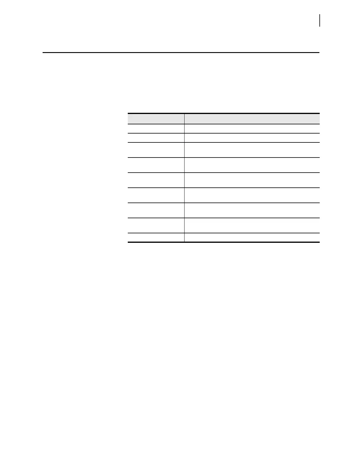
Ta b l e 1 3.1 Sum m a r y o f S E L OGIC Control Equation Elements
Element Description
Relay Word bits Boolean value data
Analog quantities Received, measured, and calculated values
Special condition bits Bits that indicate special SELOGIC control equation execution
conditions
SEL
OGIC control equation
variables
Storage locations for the results of Boolean SELOGIC control
equations
SEL
OGIC control equation
math variables
Storage locations for the results of math SELOGIC control equations
Latch bits Nonvolatile storage for the results of Boolean SEL
OGIC control
equations
Conditioning timers Pickup and dropout style timers similar to those used in SEL-300
series relays
Sequencing timers On-delay timers similar to those used in programmable logic con-
trollers
Counters Counters that count rising edges of Boolean value inputs