13.12
SEL-400 Series Relays Instruction Manual Date Code 20171006
SELOGIC Control Equation Programming
SEL
OGIC Control Equation Elements
Latch Bits
Latch bits are nonvolatile storage locations for Boolean information. Latch bits
are in several settings areas of the relay, as shown in Tab le 13.7 . Latch bits have
two input parameters, Reset and Set, and one Latched Value, as shown in
Table 13.8.
Example 13.5 SELOGIC Control Equation Math Variables
The equations below show freeform SELOGIC control equation program-
ming examples that use SEL
OGIC control equation math variables using ana-
log quantities available in the SEL-421. Each line has a comment after the #
that provides additional description.
PMV01 := 378.62 # Store 387.62 in PMV01
PMV09 := 5 + VAFM # Store sum of 5 and A-Phase voltage in kV in
PMV09
You can use SEL
OGIC control equation math variables more than once in
freeform programming. Use AMV010 in the following SEL
OGIC control
equations to calculate intermediate results.
# Determine if any phase voltage is greater than 13 kV
# A-Phase
AMV010 := VAFIM/1000 # VA in kV
ASV010 := AMV010 > 13 # Set if greater than 13 kV
# B-Phase
AMV010 := VBFIM/1000 # VB in kV
ASV011 := AMV010 > 13 # Set if greater than 13 kV
# C-Phase
AMV010 := VCFIM/1000 # VC in kV
ASV012 := AMV010 > 13 # Set if greater than 13 kV
# Combine phase results
ASV013 := ASV010 OR ASV011 OR ASV012
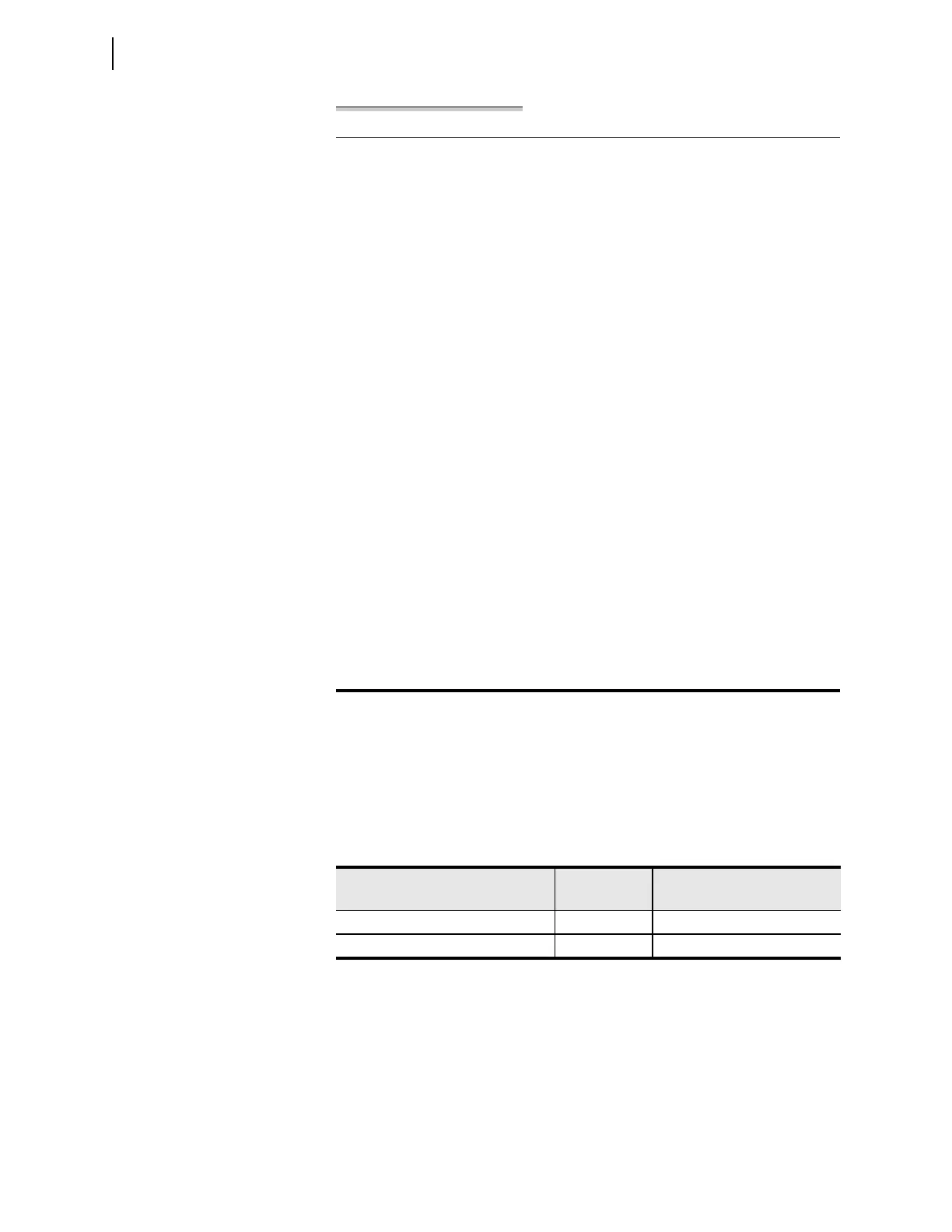
Table 13.7 Latch Bit Quantities
Type
Typic al
Quantity
Name Range
Protection freeform latch bits 32 PLT01–PLT32
Automation latch bits 32 ALT01–ALT32