15.3
Date Code 20171006 Instruction Manual SEL-400 Series Relays
Communications Interfaces
Serial Communication
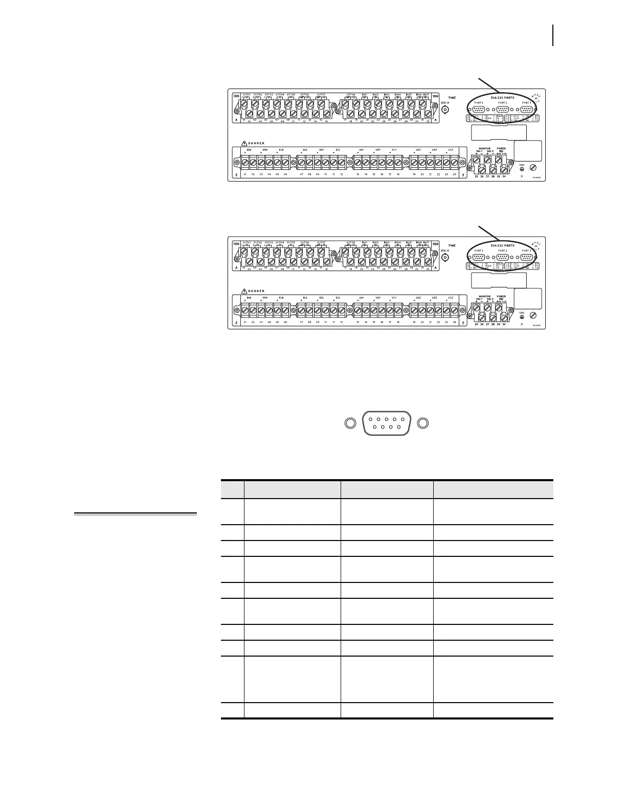
The EIA-232 ports are standard female 9-pin connectors with the pin numbering
shown in Figure 15.4. The pin functions are listed in Table 15.2. Pin 1 can pro-
vide power to an external device.
Figure 15.2 Example 3U Rear-Panel Layout
Figure 15.3 Example 4U Rear-Panel Layout in Relay With Bay Cards
Figure 15.4 EIA-232 Connector Pin Numbers
Table 15.2 EIA-232 Pin Assignments
Pin Signal Name Description Comments
1 5 Vdc Modem power Jumper selectable on PORT 1–
PORT 3. No connection on PORT F.
2 RXD Receive data
3 TXD Transmit data
4 +IRIG-B Time code signal positive PORT 1 only. No connection on
PORT F, PORT 2, and PORT 3.
5 GND Signal ground Also connected to chassis ground.
6 –IRIG-B Time code signal negative PORT 1 only. No connection on
PORT F, PORT 2, and PORT 3.
7 RTS Request to send
8 CTS Clear to send (input)
8 TX/RX CLK (for
SPEED := SYNC,
only available when
PROTO := MBA or MBB)
Transmit and receive
clock (input)
Rear-panel serial ports only
9 GND Chassis ground
NOTE: Pins 5 and 9 are not intended to
provide a chassis ground connection.