18.39
Date Code 20171006 Instruction Manual SEL-400 Series Relays
Synchrophasors
Control Capabilities
Real-Time Control Example
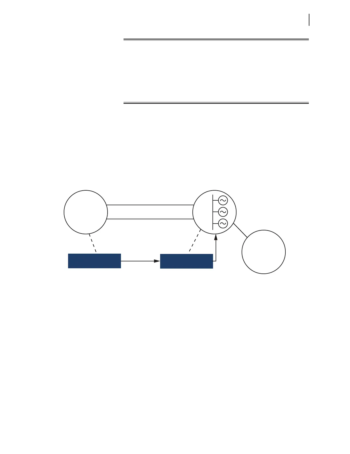
Figure 18.12 shows an application example using SEL-411L relays. In this exam-
ple, Area 2 supplies power to Area 1 and Area 3. An important contingency is
loss of both Link 1 and Link 2. In such a case, the generators in Area 2 accelerate.
Alternate paths between Area 2 and Area 1 can also become stressed beyond
their design limits. A simple solution is to measure the phase angle between
Area 1 and Area 2. When the angle exceeds a predetermined limit, control the
generation to avoid exceeding system limits.
Figure 18.13 shows the SELOGIC for the relay controlling the generator (called
the local relay in this example). Lines 1 and 2 store phasor data into PMV53 and
PMV54 so they can be viewed through use of the MET PMV command. Line 3
computes the angle difference between the local and remote relays. RTCAP02 is
the remote V1Y angle. Lines 4–10 unwrap the phase angle when the difference
exceeds ±180 degrees.
RTCROKA pulses true whenever a good synchrophasor message is received. For
purposes of this example, we need it to hold true until the next message is
received. To achieve this, lines 11-13 implement a timer to extend this bit by 1.75
cycles. A message is expected every 1 cycle; the additional 0.75 cycles covers
any jitter that may occur in the rate or message receipt. Line 14 calculates a qual-
ification signal consisting of the local and remote quality indicators. RTCROKA
is the local indicator which has been extended as PCT01. RTCAD16 is the
remote quality indicator. Figure 18.14 shows its construction at the remote relay.
Line 15 computes absolute value of the angle. Line 16 checks the angle against
the reference value. In this case, the reference value is 10 degrees.
The final result, PSV03, asserts when the relay receives a synchrophasor message
with an angle difference exceeding 10 degrees.
Summary for RTC channel A
Port: 2
ID: 8
Present Status: Receiving
Max Packet Delay: 50 msec
Message Rate: 60 msgs/sec
Summary for RTC channel B
Port: 1
ID: 9
Present Status: Receiving
Max Packet Delay: 40 msec
Message Rate: 60 msgs/sec
Figure 18.11 Example COM RTC Command Response
Figure 18.12 Real-Time Control Application
SEL-411L
SEL-411L
Area 2
Link 1
Link 2
Area 1
Heavy Load
Area 3
Light Load
Synchrophasors
Control
Generation