3.63
Date Code 20171006 Instruction Manual SEL-400 Series Relays
Basic Relay Operations
Operating the Relay Inputs and Outputs
Step 2. View the front-panel display.
After applying power to the relay, note that the LCD shows a
sequence of screens called the
ROTATING DISPLAY.
(Also, if you do not operate the front panel for a certain period, the
relay will enter front-panel time-out mode and you will see the
sequential screens of the
ROTATING DISPLAY.)
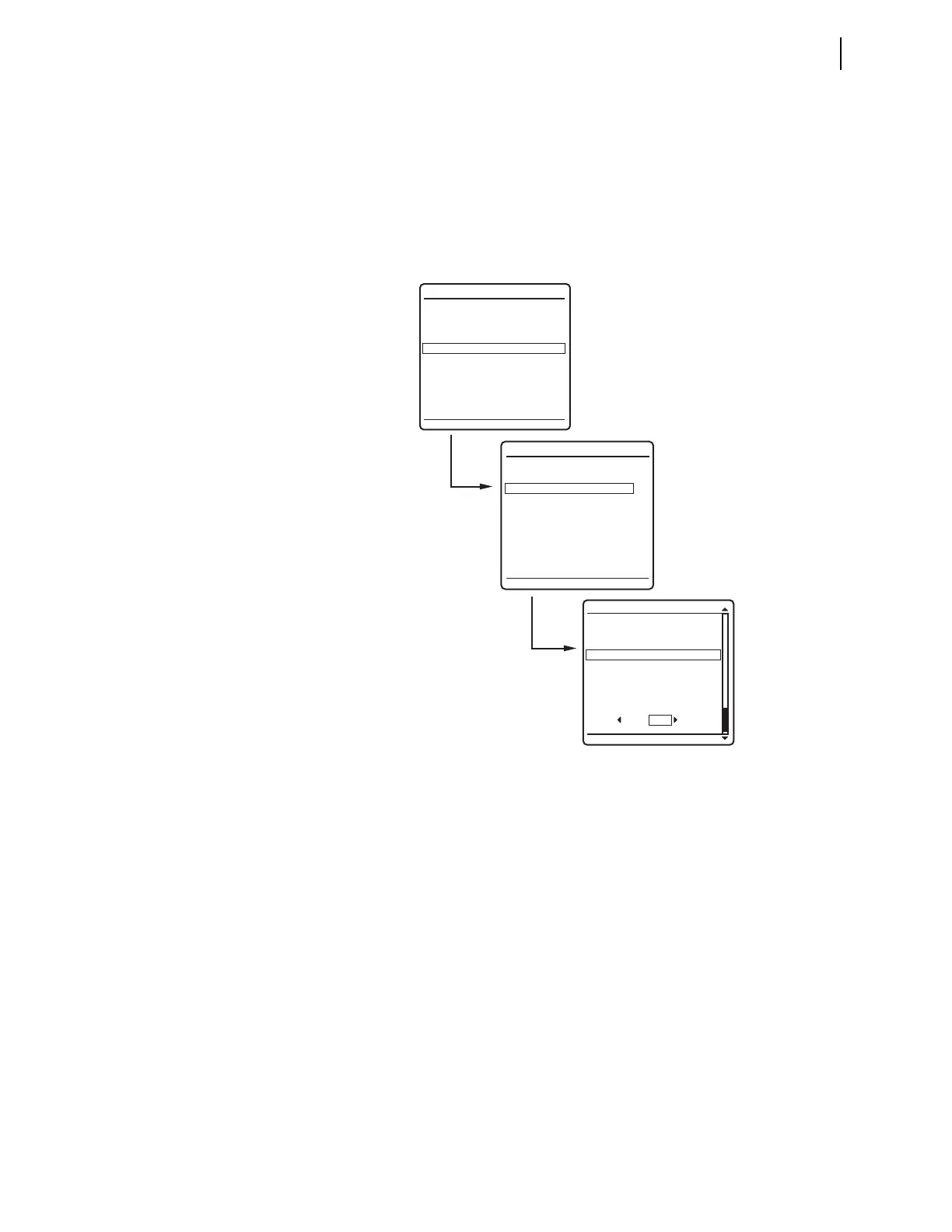
Step 3. Press the ENT pushbutton to view the
MAIN MENU, similar to that in
Figure 3.56(a).
Step 4. View the LOCAL CONTROL screen.
a. Press the Up Arrow and Down Arrow navigation pushbuttons to
highlight the
LOCAL CONTROL action item, as shown in
Figure 3.56(a).
b. Press the ENT pushbutton.
You will see the
LOCAL CONTROL submenu as shown in
Figure 3.56(b).
Step 5. View the
OUTPUT TESTING screen.
a. Press the Up Arrow and Down Arrow navigation pushbuttons to
highlight the
--OUTPUT TESTING-- action item, as shown in
Figure 3.56(b).
b. Press the ENT pushbutton.
The relay displays the
OUTPUT TESTING submenu, as shown in
Figure 3.56(c).
Figure 3.56 Front-Panel Menus for Pulsing OUT104
OUT101
OUT102
OUT103
OUT104
OUT105
OUT106
OUT107
OUT108
PULSE OUTPUT?
OUTPUT TESTING
NO YES
METER
EVENTS
BREAKER MONITOR
RELAY ELEMENTS
LOCAL CONTROL
SET/SHOW
RELAY STATUS
VIEW CONFIGURATION
DISPLAY TEST
RESET ACCESS LEVEL
MAIN MENU
LOCAL CONTROL
--BREAKER CONTROL--
5 MVA XFMR Fans
--OUTPUT TESTING--
(a)
(b)
(c)