4.6
SEL-400 Series Relays Instruction Manual Date Code 20171006
Front-Panel Operations
Front-Panel Layout
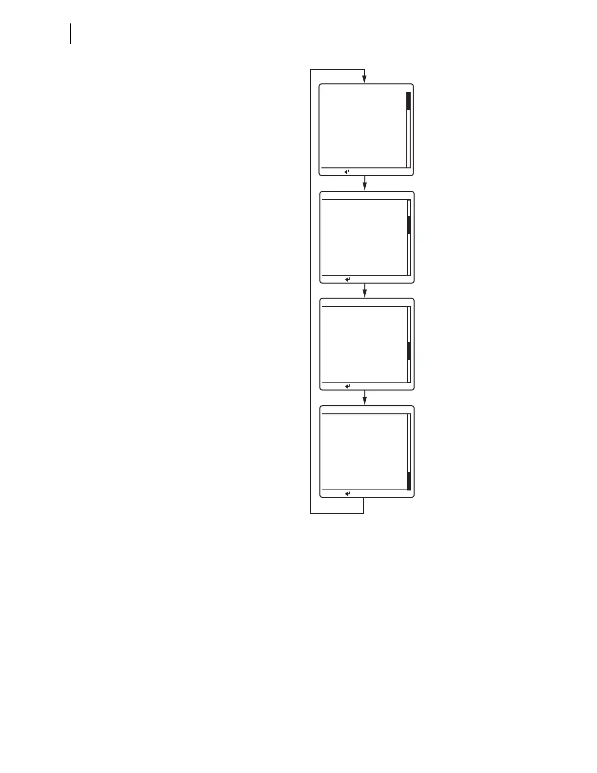
Figure 4.6 illustrates an example rotating display sequence. The active alarm
points are the first screens in the
ROTATING DISPLAY (see Alarm Points on
page 4.7). Each alarm points screen shows as many as 11 alarm conditions. The
relay can present a maximum of six alarm points screens.
The active display points are the next screens in the
ROTATING DISPLAY after
alarm points (see Display Points on page 4.10). Each display points screen shows
as many as 11 enabled display points (with 96 display points, the relay can pres-
ent a maximum of nine display points screens). If a display point does not have
text to display, the screen space for that display point is maintained.
Figure 4.6 Sample ROTATING DISPLAY
Circuit Breaker 1
--Closed--
ROTATING DISPLAY
Press for menu
Line Current (A) RMS
IA =
119.6
IB =
119.7
IC =
119.5
FREQ = 60.00 Hz
ROTATING DISPLAY
Press for menu
Line Quantities FUND
ROTATING DISPLAY
Press for menu
Voltage (kV)
VA = 130.4 + 6˚
VB = 130.3 -114˚
VC = 130.5 -126˚
Current (A)
IA = 119.6 35˚
IB = 119.7 -95˚
IC = 119.5 155˚
FREQ = 60.00 Hz
Circuit BK1 SF6 Gas
--Alarm--
Circuit Breaker 2
A PH= 119.6 A pri
*Circuit BK1 SF6 Gas
ROTATING DISPLAY
Press for menu
SF6 ALARM