5.2
SEL-400 Series Relays Instruction Manual Date Code 20171006
Control
Disconnect Logic
connect operations. All disconnect control methods (HMI, ASCII, SELOGIC
control equations, and Fast Operate) drive the Close and Open Control Logic in
the relay.
Disconnect Switch Close and Open Control Logic Status Inputs
89CLS
m
, 89OPE
m
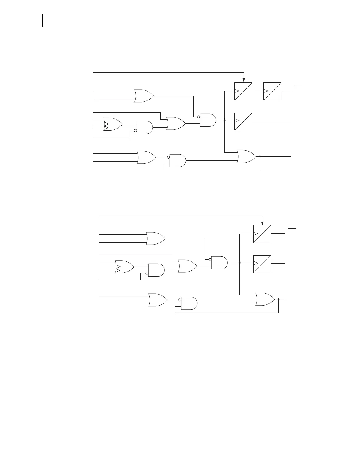
Disconnect Switch Close Logic (Figure 5.1) and Open Logic (Figure 5.2) gener-
ate Relay Word bits 89CLSm and 89OPEm which drive the open and close oper-
ations. To ensure that an open and close disconnect signal cannot occur at the
same time, 89CLSm and 89OPEm also block operation of the opposing logic.
Therefore, Relay Word bit 89CLSm is an input to the Disconnect Open Logic,
and Relay Word bit 89OPEm is an input to the Disconnect Close Logic.
Figure 5.1 Disconnect Switch Close Logic
Close Immobility Timer
89CITm
0 CYC
*89CIRm
(default setting:
NOT 89OPNm)
89ALm
*89CRSm
(default setting:
89CLm OR 89CSIm)
Relay
Word
Bits
* SELOGIC control equation
** This SELOGIC control equation
processed at 1/8 cycle
89CIMm
89CLSm
(Reset)
0 CYC
60
CYC
5
2
3
Close Seal-in Timer
89CSTm
0
CYC
*89CBLm
89OPEm
89CCMm
89CCm (ASCII)
**89CCNm (k – 1/8 cyc.)
**89CCNm (k)
*LOCAL
89CSIm
3
4
2
1
1
Figure 5.2 Disconnect Switch Open Logic
Open Immobility Timer
89OITm
60
CYC
*89OIRm
(default setting:
NOT 89CLm)
89ALm
*89ORSm
(default setting:
89OPNm OR 89OSIm)
Relay
Word
Bits
* SELOGIC control equation
** This SELOGIC control equation
processed at 1/8 cycle
89OIMm
89OPEm
(Reset)
5
2
3
Open Seal-in Timer
89OSTm
0
CYC
*89OBLm
89CLSm
89OCMm
89OCm (ASCII)
**89OCNm (k – 1/8 cyc.)
**89OCNm (k)
*LOCAL
89OSIm
3
4
2
1
1