5.12
SEL-400 Series Relays Instruction Manual Date Code 20171006
Control
Bay Control Front-Panel Operations
control equations. Remote bits can be operated from multiple communications
interfaces, including the CON command from a terminal (serial or Telnet), Fast
Operate messages, and DNP3.
A pulsed remote bit will assert the respective remote bit Relay Word bit (RBnn,
nn = 01–32) for one processing interval (1/8 of a power system cycle). When
used in Protection SEL
OGIC, which also executes at one processing interval,
pulsed remote bits provide a momentary means for operating a variety of logic
functions, including Protection Latches, Boolean logic expressions, and Protec-
tion Logic Counters. Because the pulsed remote bit and Protection processing
both operate within the same processing interval, the use of pulsed remote bits is
reliable and deterministic.
To provide reliable detection of pulsed remote bits that assert for one protection
logic processing interval within automation logic, conditioning is applied to the
remote bit to extend the momentary assertion through the automation processing
interval. This conditioning ensures the reliable detection of remote bit (RB01–
RB32) assertion in automation logic. Remote bits that assert and deassert multi-
ple times within the same automation logic processing interval will be processed
as asserting continuously for the entire automation logic processing interval.
Bay Control Front-Panel Operations
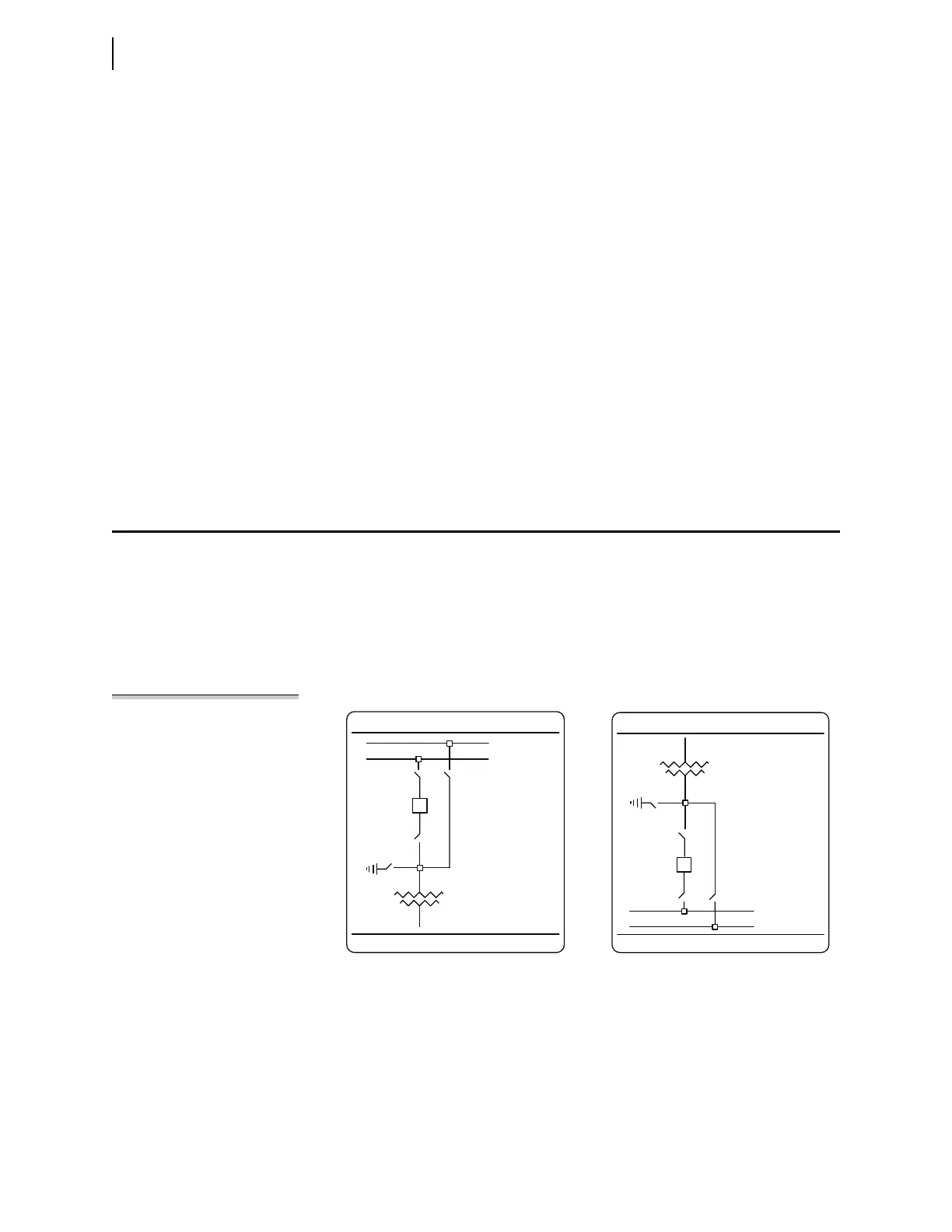
Each relay has a default one-line diagram. Sometimes these diagrams fit on a sin-
gle screen and sometimes they require more than one screen that you can pan
across. For example, Figure 5.7 shows the default one-line diagram for the
SEL-487E. You can display either of two parts of the diagram by using the
Up Arrow and Down Arrow pushbuttons to pan between an upper screen and a lower
screen. The upper screen shows the HV equipment and transformer, while the
lower screen shows the transformer and LV equipment. The relay displays the
upper screen by default.
NOTE: Not all SEL-400 series relays
support bay control operations.
Figure 5.7 SEL-487E Default One-Line Diagram
BUSNAM 1
BUSNAM 2
SW 2
AQ _1
AQ _2
AQ _3
AQ _4
SW1
BKS
SW3
SW4
EQ1
BAY 1
EQ 1
SW5
SW6
BKT
SW7 SW 8
AQ _5
AQ _6
AQ _7
AQ _8
BUSNAM 3
BUSNAM4
BAY 1
Upper Pan Area Lower Pan Area