5.16
SEL-400 Series Relays Instruction Manual Date Code 20171006
Control
Bay Control Front-Panel Operations
The one-line diagram indicates highlighted text with a box around the current
selection.
Circuit Breaker and Disconnect Switch Operations From the Front Panel
Circuit Breaker Open/Close
Figure 5.9 shows the Breaker Control Screens available after pressing the ENT
pushbutton (
ONELINE bay control screen), with the circuit breaker highlighted
(Only highlighted breakers on the one-line diagram can initiate breaker open or
close operations). Pressing the ENT pushbutton with the breaker highlighted and
the LOCAL Relay Word bit asserted displays the Breaker Control Screen in
Figure 5.9(b). If the LOCAL Relay Word bit is not asserted when the ENT push-
button is pressed, the relay displays the screen in Figure 5.9(c) for three seconds
and then returns to the screen in Figure 5.9(a).
Disconnect Operation In Progress,
not highlighted
b
89OIPm
Disconnect Operation In Progress,
highlighted
c
89OIPm
a
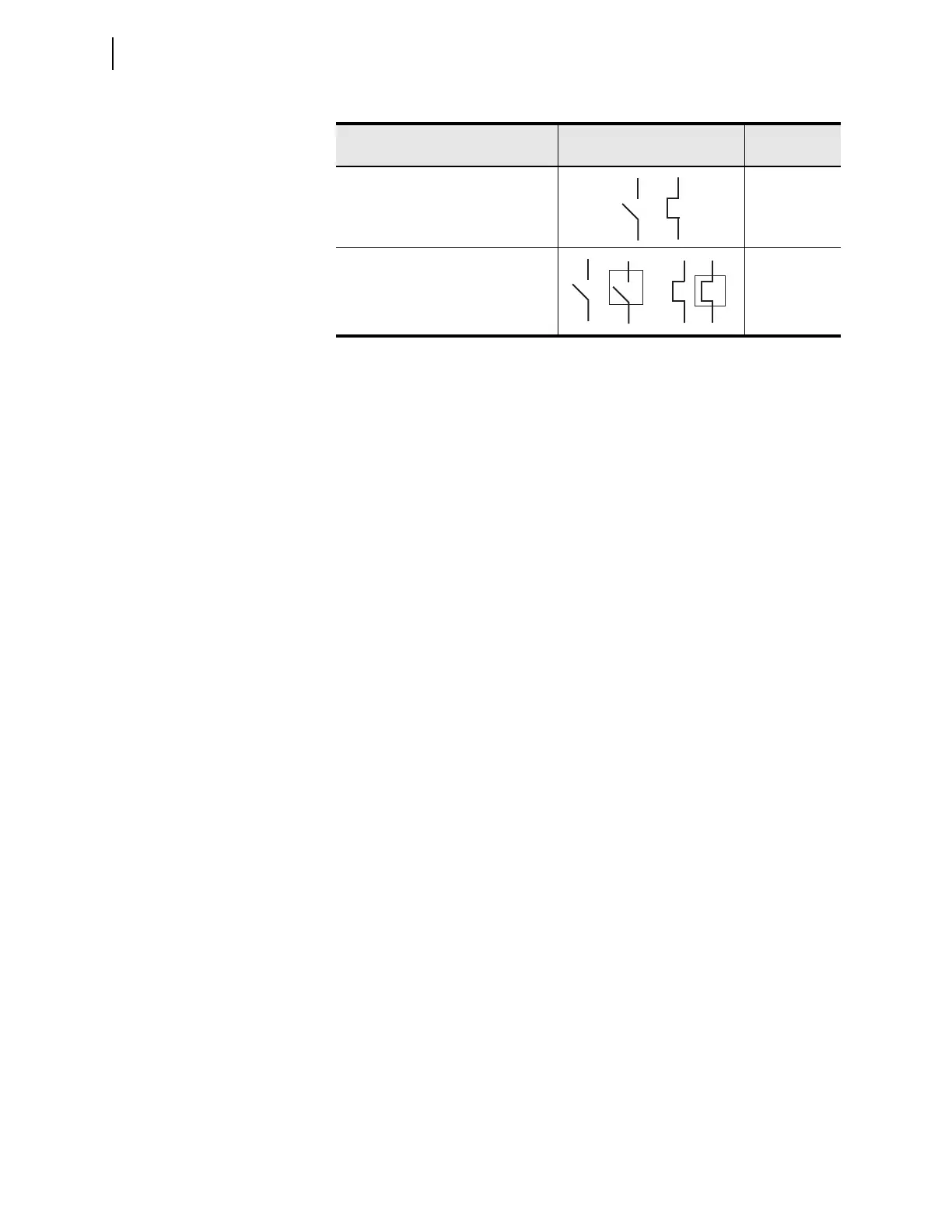
When the disconnect switch is highlighted and no operation is in progress, a square box
alternately frames the switch symbol.
b
For a disconnect switch operation in progress where the disconnect switch is not highlighted, the
symbol displayed is the present state symbol and then the opposite state symbol. This sequence
repeats until the disconnect switch operation completes.
c
For a disconnect switch operation in progress where the disconnect is highlighted, the symbol
displayed is the present state symbol, then the present state symbol highlighted, then the
opposite state symbol, and finally the opposite state symbol highlighted. This sequence repeats
until the disconnect switch operation completes.
Table 5.3 Disconnect Switch State Representations (Sheet 2 of 2)
Apparatus Position Symbol
Asserted Relay
Word Bit