5.15
Date Code 20171006 Instruction Manual SEL-400 Series Relays
Control
Bay Control Front-Panel Operations
Table 5.3 describes how the one-line diagram represents the different states of the
disconnect switches, and how highlighting the disconnect switch affects the dis-
play of the symbol. Unlike the fast operation time of the circuit breaker, the dis-
connect switch operation-in-progress time is longer than the breaker operation
time. Ta ble 5 . 3 describes how apparatus appear in the one-line diagram when a
disconnect operation is in progress.
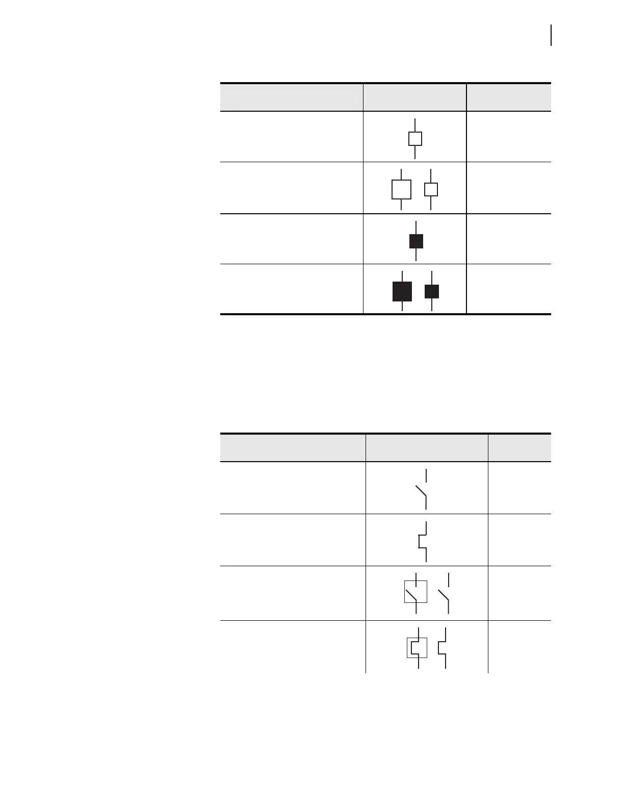
Table 5.2 Circuit Breaker State Representations
Apparatus Position Symbol
Asserted Relay
Word Bit
Circuit breaker open, not highlighted
NOT 52CLSMm
Circuit breaker open, highlighted
a
a
When the circuit breaker is highlighted, the two symbols shown alternate in the display.
NOT 52CLSMm
Circuit breaker closed, not highlighted
52CLSMm
Circuit breaker closed, highlighted
52CLSMm
Table 5.3 Disconnect Switch State Representations (Sheet 1 of 2)
Apparatus Position Symbol
Asserted Relay
Word Bit
Disconnect open, not highlighted
89OPNm
Disconnect closed, not highlighted
89CLm
Disconnect open, highlighted
a
89OPNm
Disconnect closed, highlighted
a
89CLm