5.24
SEL-400 Series Relays Instruction Manual Date Code 20171006
Control
Bay Control Front-Panel Operations
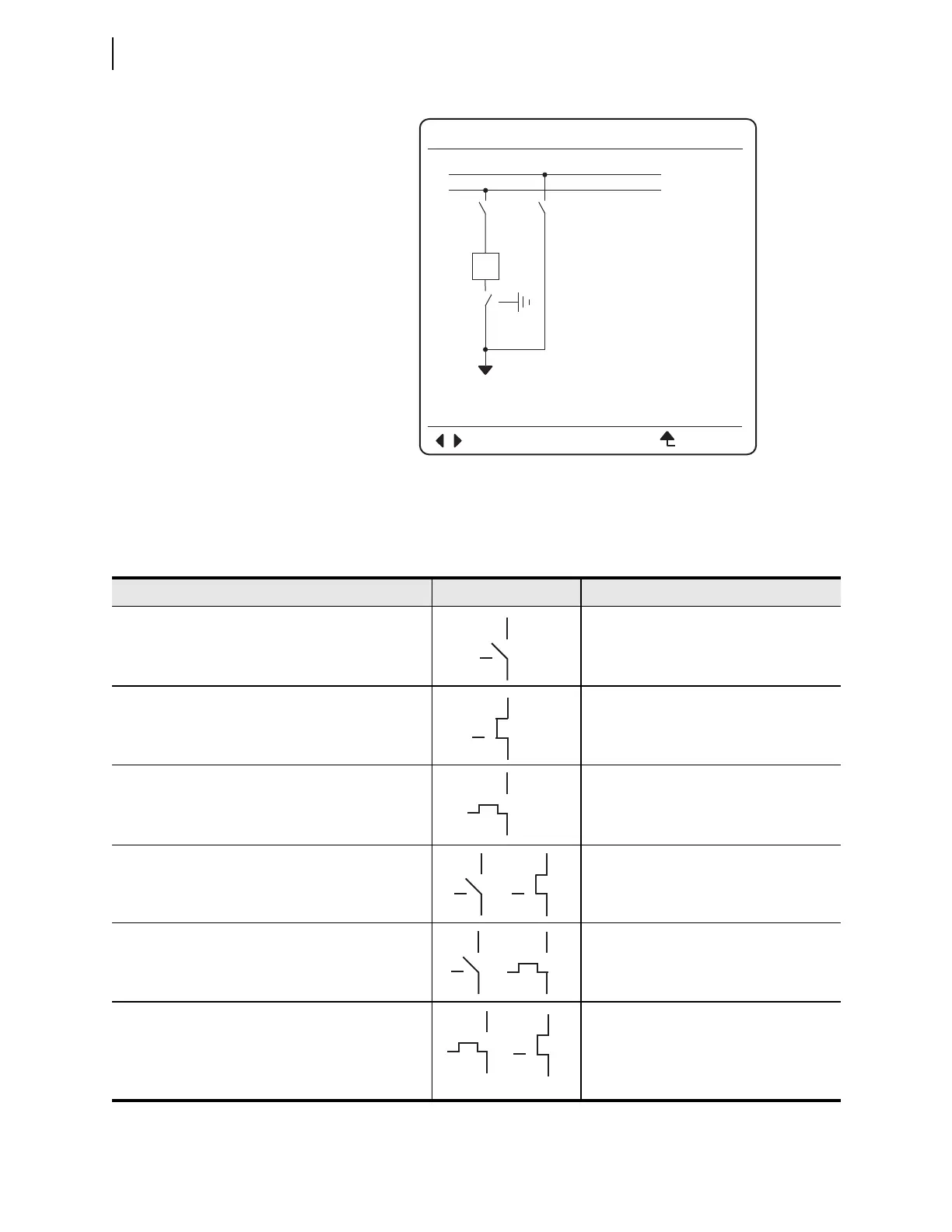
Table 5.4 displays how the bay screen one-line diagram represents the different
states of the three-position disconnect switch.
Figure 5.15 Bay Control One-Line Diagram With Three-Position Disconnect Open
BAYNAME
ESCNAVIG
I:9999A
V:99999kV
P:99999MW
Q:99999MV
BUS 1
SW3
SW4
BK1
SW1 SW2
BUS 2
Table 5.4 Three-Position Disconnect Switch State Representations
Apparatus Position Symbol Asserted Relay Word Bits
Both disconnects open
89OPN3 and 89OPN4
Disconnect 3 (in-line) closed
Disconnect 4 (ground) opened
89CL3 and 89OPN4
Disconnect 3 (in-line) opened
Disconnect 4 (ground) closed
89OPN3 and 89CL4
Disconnect 3 (in-line) intermediate
a
Disconnect 4 (ground) opened
b
(89OIP3 or 89AL3) and 89OPN4
Disconnect 3 (in-line) opened
Disconnect 4 (ground) intermediate
a
b
89OPN3 and (89OIP4 or 89AL4)
All other status combinations
Disconnect 3 closed, Disconnect 4 closed
Disconnect 3 closed, Disconnect 4 intermediate
a
Disconnect 3 intermediate
a
, Disconnect 4 closed
Disconnect 3 intermediate
a
, Disconnect 4 intermediate
a
b
89CL3 and 89CL4
89CL3 and (89OIP4 or 89AL4)
(89OIP3 or 89AL3) and 89CL4
(89OIP3 or 89AL3) and (89OIP4 or 89AL4)
a
Intermediate = transition between open and closed states.
b
The image alternates between the two symbols shown.