6.22
SEL-400 Series Relays Instruction Manual Date Code 20171006
Autoreclosing
Two-Circuit-Breaker Autoreclosing
Example Four: Input Selection of Leader
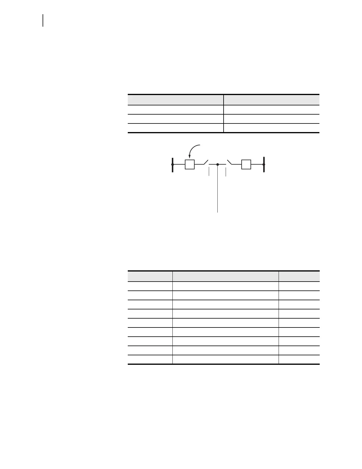
Figure 6.4 illustrates a circuit breaker-and-a half configuration for this particular
example. The leader and follower selection settings are shown in Table 6.17. Cir-
cuit Breaker BK1 is out of service for maintenance and Disconnect Switch 1 is
open.
Table 6.18 defines the logical state of the autoreclose logic for this example prior
to the initiation of an autoreclose cycle. These conditions are frozen during an
autoreclose cycle. The relay autoreclose logic can unfreeze these conditions if the
relay receives another initiation.
Enable Autoreclose Logic for Two Circuit Breakers
Three-Pole Trip Circuit Breakers
The initial settings necessary to enable autoreclose for two three-pole trip circuit
breakers are shown in Table 6.19.
Table 6.17 Leader/Follower Selection
Setting Label Setting
SLBK1 IN106 (Disconnect 1 a contacts)
SLBK2 IN107 (Disconnect 2 a contacts)
FBKCEN 0
Figure 6.4 Leader/Follower Selection by Relay Input
Table 6.18 Two Circuit Breakers: Circuit Breaker BK1 Out of Service
Relay Word Bit Description Logical State
NBK0 No Active Breakers in Reclose Scheme 0
NBK1 One Breaker Active in Reclose Scheme 1
NBK2 Two Active Breakers in Reclose Scheme 0
LEADBK0 No Leader Breaker 0
LEADBK1 Leader Breaker = Breaker 1 0
LEADBK2 Leader Breaker = Breaker 2 1
FOLBK0 No Follower Breaker 1
FOLBK1 Follower Breaker = Breaker 1 0
FOLBK2 Follower Breaker = Breaker 2 0
Bus 1
(Leader)
Line
to IN106 to IN107
Out of Service
(maintenance)
Bus 2
BK2
BK1