Procedure
1. The part program or ShopTurn program to be processed has been cre‐
ated and you are in the editor.
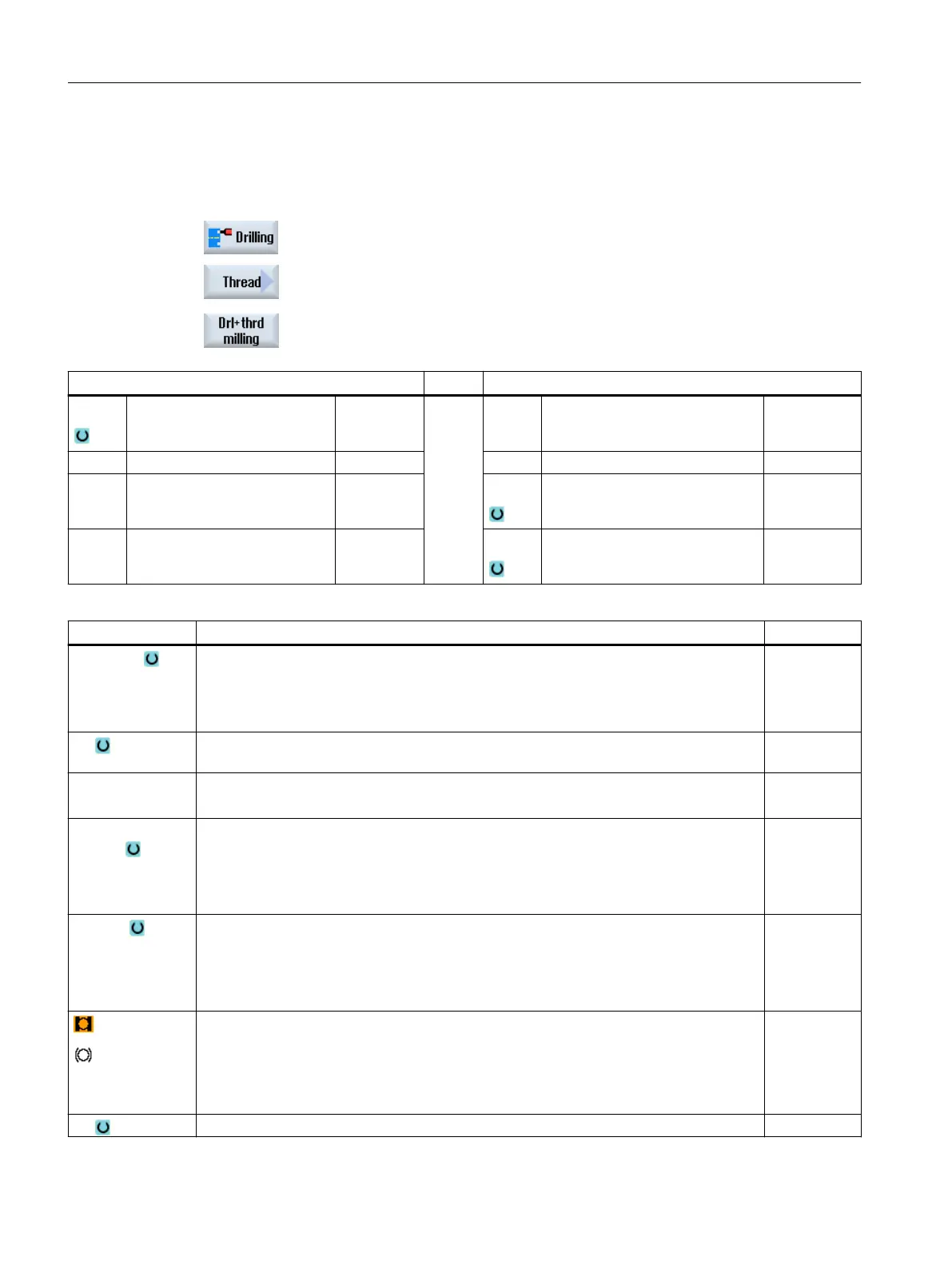
2. Press the "Drilling" softkey.
3. Press the "Thread" and "Cut thread" softkeys.
The "Drilling and thread milling" input window opens.
Parameters, G code program Parameters, ShopTurn program
PL Machining plane T Tool name
RP Retraction plane mm D Cutting edge number
SC Safety clearance mm F Feedrate mm/min
mm/rev
S / V Spindle speed or constant cutting
rate
rpm
m/min
Parameters Description Unit
Machining posi‐
tion
(only for G code)
● Single position
Drill hole at programmed position
● Position pattern
Position with MCALL
F1
(only for G code)
Drilling feedrate mm/min
mm/rev
Z0
(only for G code)
Reference point Z mm
Machining
surface
(only for Shop‐
Turn)
● Face C
● Face Y
● Peripheral surface C
● Peripheral surface Y
Position
(only for Shop‐
Turn)
● At the front (face)
● At the rear (face)
● Outside (peripheral surface)
● Inside (peripheral surface)
(only for Shop‐
Turn)
Clamp/release spindle (only for end face Y/peripheral surface Y)
The function must be set up by the machine manufacturer.
Z1 Thread length (inc) or end point of the thread (abs) mm
Programming technology functions (cycles)
10.1 Drilling
Turning
382 Operating Manual, 06/2019, A5E44903486B AB