10.6.2.2 Aligning milling tools - only for G code program (CYCLE800)
Procedure
1. The part program to be executed has been created and you are in the
editor.
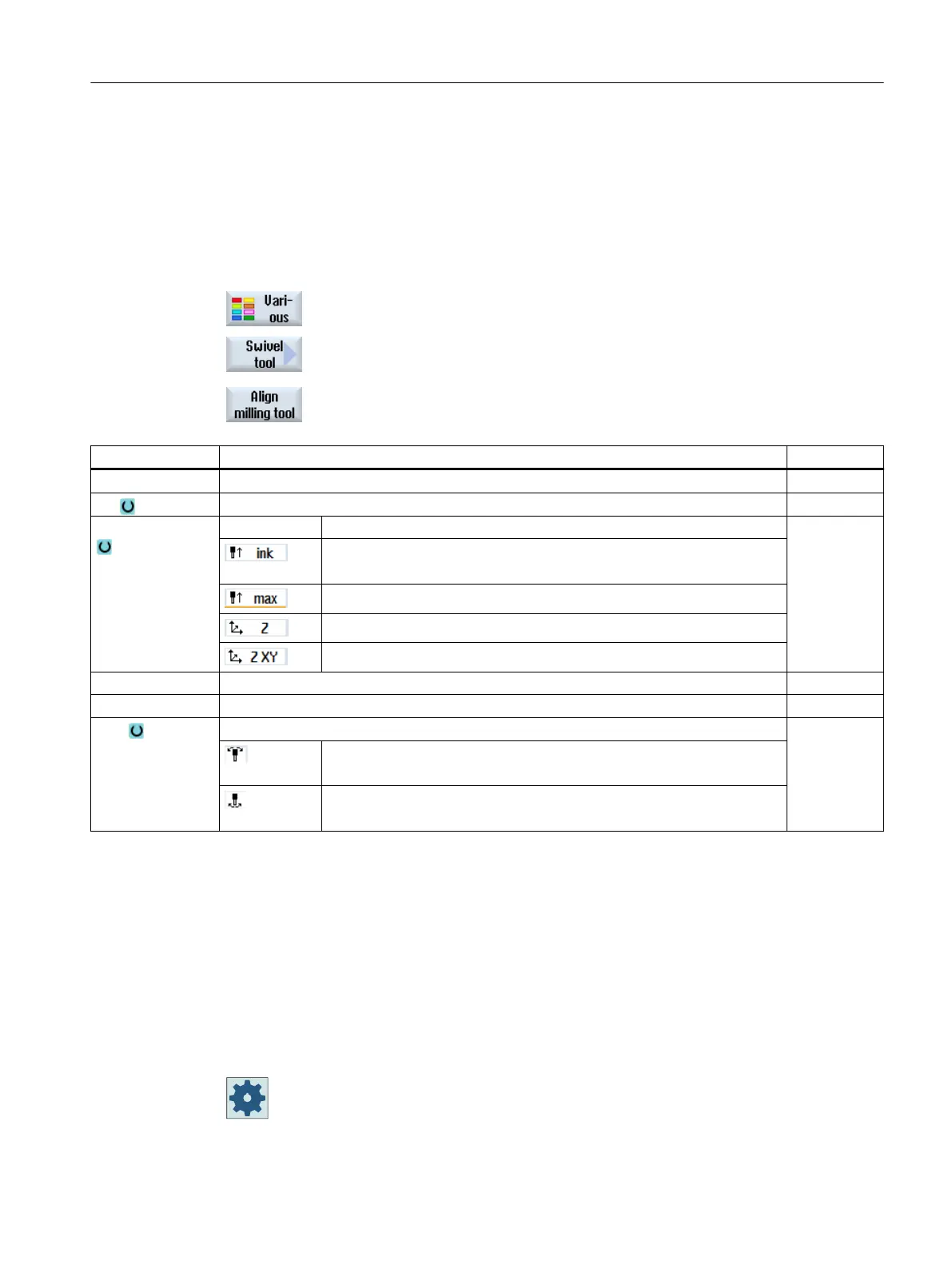
2. Press the "Various" softkey.
3. Press the "Swivel tool" and "Align milling tool" softkeys.
The "Align milling tool" input window opens.
Parameter Description Unit
PL Plane for milling
TC Name of the swivel data record
Retraction No No retraction before swiveling
Incremental retraction in tool direction
The retraction path is entered into parameter ZR.
Maximum retraction in tool direction
Retraction in the direction of machine axis Z
Retract towards the machine axis Z and then in the direction X, Y
ZR Retraction path - (only for incremental retraction in the tool direction)
β Rotation around the 3rd geometry axis (for G18 Y) Degrees
Tool Tool tip position when swiveling
Tracking
The position of the tool tip is maintained during swiveling.
No tracking
The position of the tool tip changes during swiveling.
10.6.2.3 Preloading milling tools - only for G code program (CYCLE800)
After "Swivel plane", the tool orientation is always perpendicular on the machining plane. When
milling with radial cutters, it can make technological sense to set the tool at an angle to the
normal surface vector. In the swivel cycle, the setting angle is generated by an axis rotation
(max. +/- 90 degrees) to the active swivel plane. When setting, the swivel plane is always
“additive”. With "Setting tool", only rotations are displayed on the swivel cycle input screen form.
The user can freely select the rotation sequence.
Machine manufacturer
Please refer to the machine manufacturer's specifications.
Programming technology functions (cycles)
10.6 Further cycles and functions
Turning
Operating Manual, 06/2019, A5E44903486B AB 615