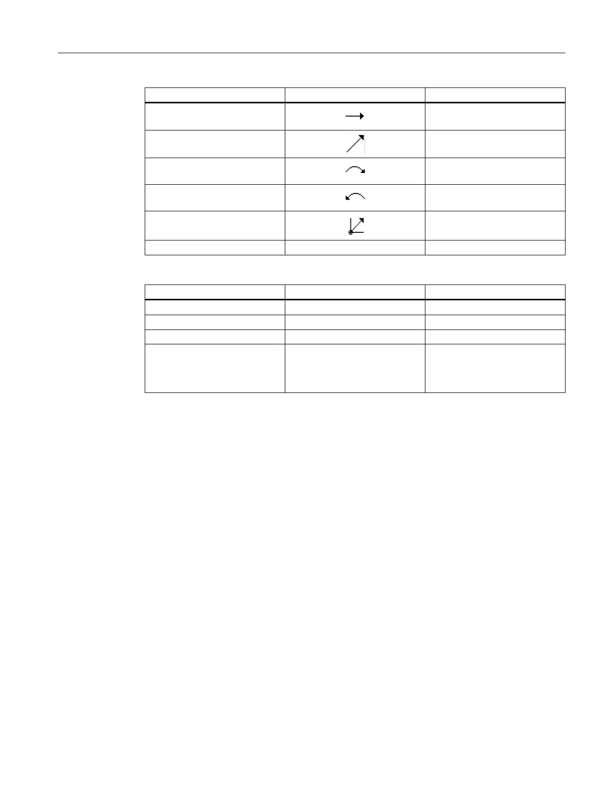
Contour element Symbol Meaning
Straight line right Straight line in 90° grid
Straight line in any direction Straight line with any gradient
Arc right Circle
Arc left Circle
Pole Straight diagonal or circle in po‐
lar coordinates
Finish contour END End of contour definition
The different colors of the symbols indicate their status:
Foreground Background Meaning
Black Blue Cursor on active element
Black Orange Cursor on current element
Black White Normal element
Red White Element not currently evaluated
(element will only be evaluated
when it is selected with the cur‐
sor)
Graphic display
The progress of contour programming is shown in broken-line graphics while the contour
elements are being entered.
When the contour element has been created, it can be displayed in different line styles and
colors:
● Black: Programmed contour
● Orange: Current contour element
● Green dashed: Alternative element
● Blue dotted: Partially defined element
The scaling of the coordinate system is adjusted automatically to match the complete contour.
The position of the coordinate system is displayed in the graphics window.
10.5.3 Creating a new contour
Function
For each contour that you want to mill, you must create a new contour.
Programming technology functions (cycles)
10.5 Contour milling
Turning
Operating Manual, 06/2019, A5E44903486B AB 565