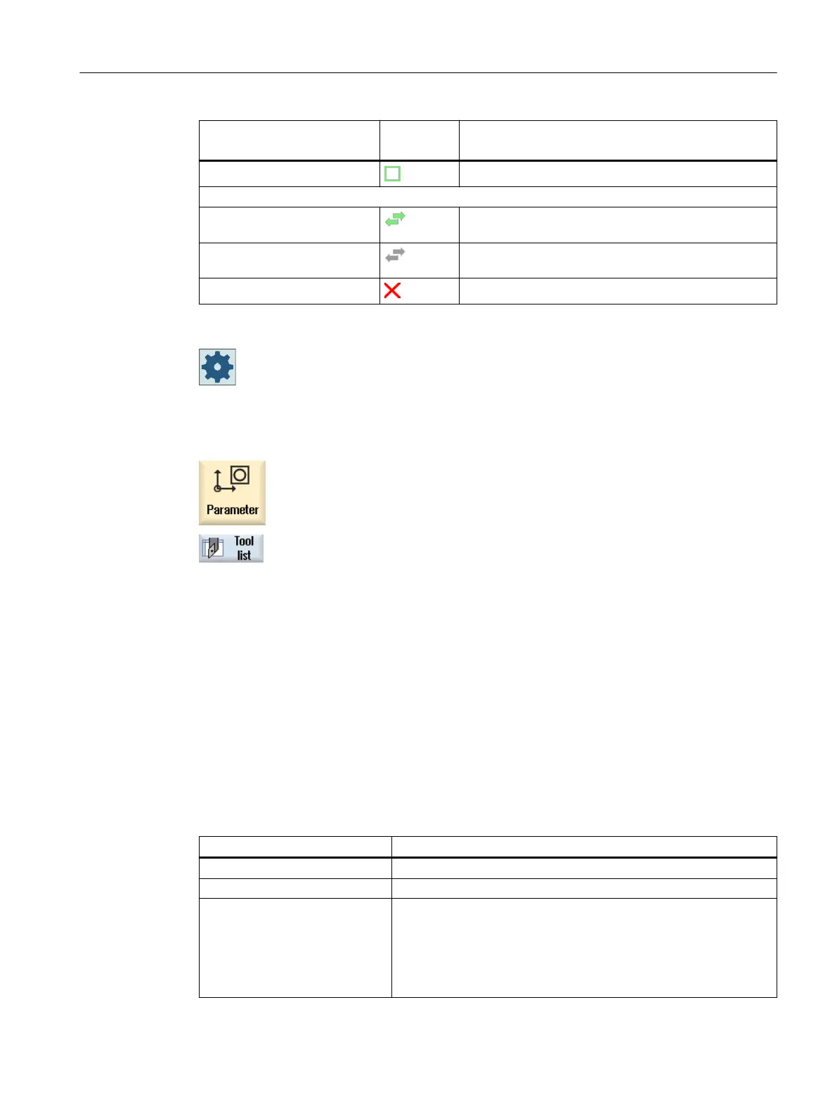
Icon/
Marking
Meaning
Green frame The tool is preselected.
Magazine/location number
Green double arrow The magazine location is positioned at the change po‐
sition.
Gray double arrow The magazine location is positioned at the loading po‐
sition.
Red "X" The magazine location is disabled.
Machine manufacturer
Please refer to the machine manufacturer's specifications.
Procedure
1. Select the "Parameter" operating area.
2. Press the "Tool list" softkey.
The "Tool List" window opens.
See also
Displaying tool details (Page 753)
Changing the cutting edge position or tool type (Page 762)
13.5.1 Additional data
The following tool types require geometry data that is not included in the tool list display.
Tool types with additional geometry data
Tool type Additional parameters
111 Conical ballhead cutter Corner radius
121 End mill with corner rounding Corner radius
130 Angle head cutter Geometry length (length X, length Y, length Z)
Wear length (Δ length X, Δ length Y, Δ length Z)
Adapter length (length X, length Y, length Z)
V (direction vector 1 - 6)
Vector X, vector Y, vector Z
Tool management
13.5 Tool list
Turning
Operating Manual, 06/2019, A5E44903486B AB 731