Parameter Description Unit
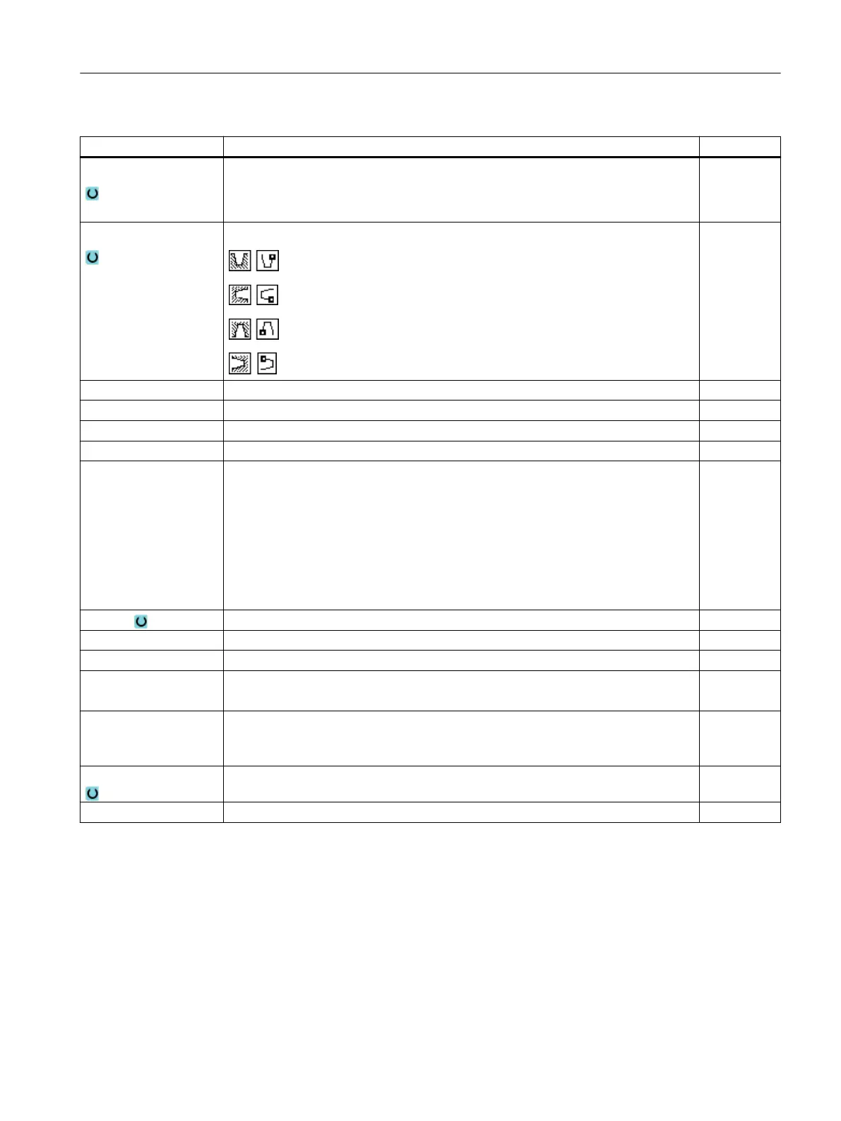
Machining
● ∇ (roughing)
● ∇∇∇ (finishing)
● ∇ + ∇∇∇ (roughing and finishing)
Position Groove position:
X0 Reference point in X ∅ mm
Z0 Reference point in Z mm
B1 Groove width mm
T1 Groove depth ∅ (abs) or groove depth referred to X0 or Z0 (inc) mm
D
● Maximum depth infeed for insertion – (only for ∇ and ∇ + ∇∇∇)
● For zero: Insertion in a cut – (only for ∇ and ∇ + ∇∇∇)
D = 0: 1. cut is made directly to final depth T1
D > 0: 1st and 2nd cuts are made alternately to infeed depth D, in order to achieve
a better chip flow and prevent the tool from breaking, refer to approaching/retraction
when roughing.
Alternate cutting is not possible if the tool can only reach the groove base at one
position.
mm
UX or U Finishing allowance in X or finishing allowance in X and Z – (only for ∇ and ∇ + ∇∇∇) mm
UZ Finishing allowance in Z – (for UX, only for ∇ and ∇ + ∇∇∇) mm
N Number of grooves (N = 1....65535)
DP Distance between grooves (inc)
DP is not displayed when N = 1
mm
α1, α2 Flank angle 1 or flank angle 2 - (only for grooves 2 and 3)
Asymmetric grooves can be described by separate angles. The angles can be be‐
tween 0 and < 90°.
Degrees
FS1...FS4 or R1...R4 Chamfer width (FS1...FS4) or rounding radius (R1...R4) - (only for grooves 2 and 3) mm
α0 Angle of the incline – (only for groove 3) Degrees
* Unit of feedrate as programmed before the cycle call
Programming technology functions (cycles)
10.2 Rotate
Turning
Operating Manual, 06/2019, A5E44903486B AB 411