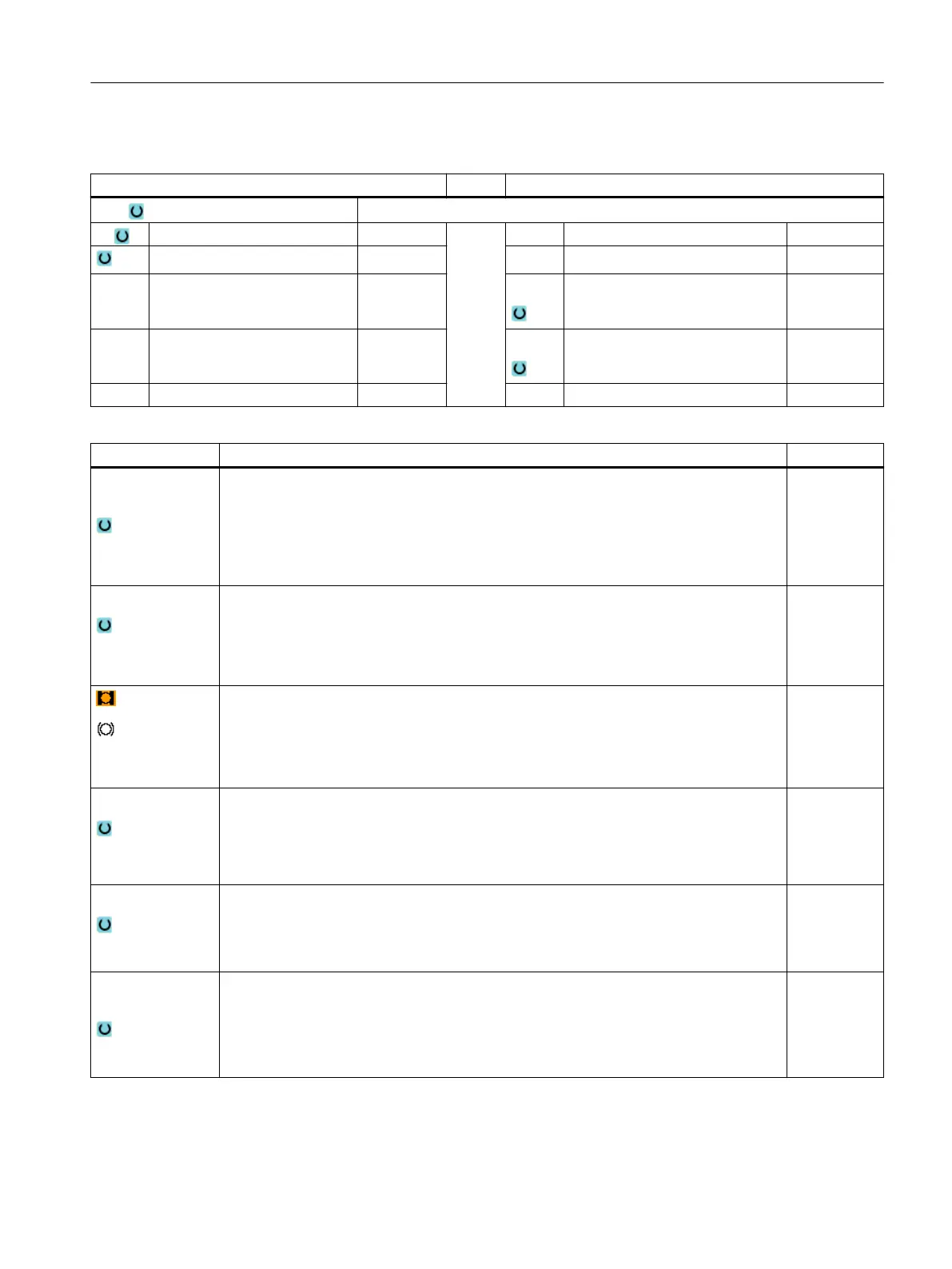
Parameters in the "Input complete" mode
G code program parameters ShopTurn program parameters
Input
● Complete
PL Machining plane T Tool name
Milling direction D Cutting edge number
RP Retraction plane mm F Feedrate mm/min
mm/tooth
SC Safety clearance mm S / V Spindle speed or constant cutting
rate
rpm
m/min
F Feedrate *
Parameter Description Unit
Machining
surface
(only for Shop‐
Turn)
● Face C
● Face Y
● Peripheral surface C
● Peripheral surface Y
Position
(only for Shop‐
Turn)
● At the front (face)
● At the rear (face)
● Outside (peripheral surface)
● Inside (peripheral surface)
(only for Shop‐
Turn)
Clamp/release spindle (only for end face Y/peripheral surface Y)
The function must be set up by the machine manufacturer.
Machining
● ∇ (roughing, plane-by-plane or helical)
● ∇∇∇ (finishing, plane-by-plane or helical)
● ∇∇∇ edge (edge finishing, plane-by-plane or helical)
● Chamfering
Machining type
● Plane by plane
Solid machine circular pocket plane-by-plane
● Helical
Solid machine circular pocket helically
Machining posi‐
tion
● Single position
A circular pocket is machined at the programmed position (X0, Y0, Z0).
● Position pattern
Several circular pockets are machined in a position pattern
(e.g. full circle, pitch circle, grid, etc.).
Programming technology functions (cycles)
10.4 Milling
Turning
Operating Manual, 06/2019, A5E44903486B AB 501