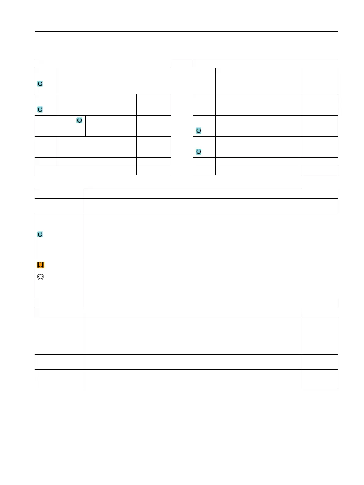
G code program parameters ShopTurn program parameters
PRG
● Name of the program to be generated
● Automatic
Automatic generation of program names
T Tool name
PL Machining plane D Cutting edge number
Milling direction
● Climbing
● Conventional
F Feedrate mm/min
mm/tooth
RP Retraction plane mm S / V Spindle speed or constant cutting
rate
rpm
m/min
SC Safety clearance mm
F Feedrate mm/min
Parameter Description Unit
TR Reference tool Tool, which is used in the "stock removal" machining step. This is used to
determine the plunge position.
Machining
surface
(only for Shop‐
Turn)
● Face C
● End face Y (only when Y axis exists)
● Face B
● Peripheral surface C
● Peripheral surface Y (only when Y axis exists)
(only for Shop‐
Turn)
Clamp/release spindle (only for end face Y/B and peripheral surface Y)
The function must be set up by the machine manufacturer.
Z0 Reference point in the tool axis Z mm
Z1 Pocket depth ∅ (abs) or depth referred to Z0 mm
CP Positioning angle for machining area
- (only for ShopTurn, machining surface, face Y)
Angle CP does not have any effect on the machining position in relation to the workpiece.
It is only used to position the workpiece with the rotary axis C in such a way that machining
is possible on the machine.
Degrees
C0 Positioning angle for machining surface
- (only for ShopTurn, machining surface, peripheral surface Y)
Degrees
DXY
● Maximum plane infeed
● Maximum plane infeed as a percentage of the milling cutter diameter
mm
%
Programming technology functions (cycles)
10.5 Contour milling
Turning
Operating Manual, 06/2019, A5E44903486B AB 585