442703/B
101
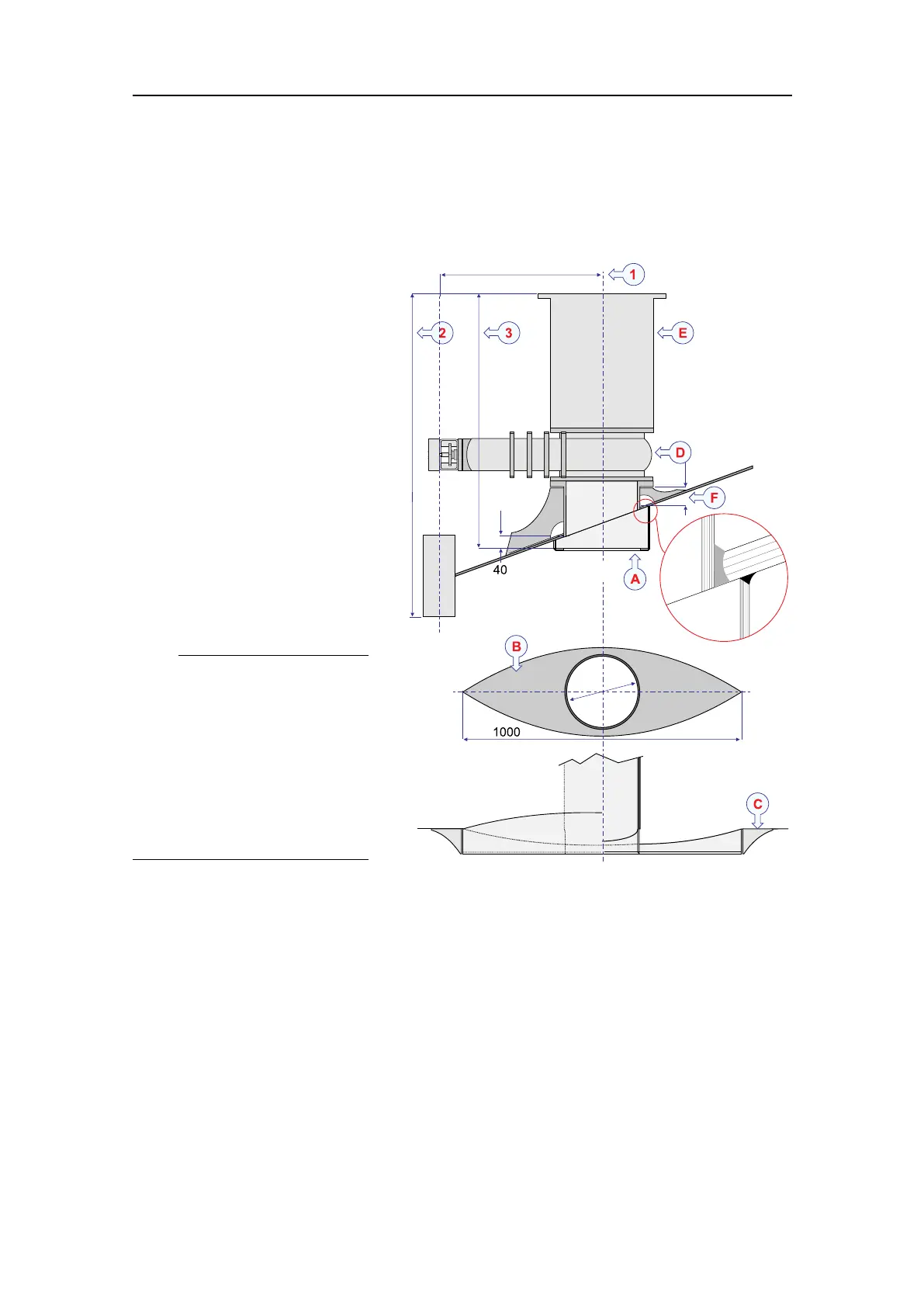
Installationexample
Thisillustrationdemonstratesthemountingprinciplesforahydraulicgatevalve.The
mountingange,gatevalveandtransducerdockareshown.Thedrawingisnottoscale.
ABlister
BBlister(shown90degrees)
CDeectionbracketsmust
onlybeweldedtothe
shell-plating.
DGatevalve
ETransducerdock
FAllowamplespacefor
weldingandinspection.
Allmeasurementsareinmm.
Thekeymeasurementsare:
1Asshortapossible
2Asshortapossible
3Asshortapossible
Note
TheST94HullUnitisdesigned
tolowerthetransducer2.1
meterbelowtheship’ shull.
Thisdepthisdecreasedwith
thephysicalheightofthegate
valve.Itisfurtherdecreased
withtheheightofthemounting
ange.
Relatedtopics
InstallingtheoptionalgatevalveDN500,page85
Gatevalveinstallationoverview,page86
082973MountingangeDN500,page446
InstallingtheoptionalgatevalveDN500