Home
Simrad
Sonar
ST90
Installation Manual
Page 436 (Installation Trunk Drawings)
Simrad ST90 - Installation Trunk Drawings
536 pages
Manual
Save Page as PDF
To Next Page
To Next Page
To Previous Page
To Previous Page
Loading...
434
442703/B
Installation
trunk
dra
wings
T
opics
436691
Installation
trunk
dimensions,
page
435
207485
Blind
ange
dimensions
(ø760
mm),
page
438
439413
T
runk
extender
(350
mm),
page
439
374676
T
runk
extender
(180
mm),
page
442
Simrad
ST90
Installation
Manual
435
437
Table of Contents
Main Page
Table of Contents
5
About this Manual
17
Simrad St90
19
Important
19
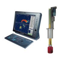
System Description
21
Key Features
23
System Diagram
24
System Units
25
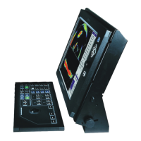
Display Description
25
Processor Unit Description
25
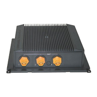
Transceiver Unit Description
26
Operating Panel Description
28
Hull Unit Description
29
Transducer Description
31
Installation Trunk Description
32
Scope of Supply
34
Basic Items Provided with a Standard Delivery
34
Additional Required Items
37
Additional Optional Items
41
General Safety Rules
48
Installation Requirements
49
Supply Power Requirements
49
Uninterruptible Power Supply (UPS) Requirements
49
Cables and Wiring Requirements
50
Compass Deviation Requirements
50
Related Topics
50
Noise Sources
51
Dry Docking Requirements
51
Requirement for Classification Approval
51
Network Security
52
Support Information
53
Preparations
55
Installation Summary
56
About Installation Drawings
59
Tools, Equipment and Consumables Required for ST90 Installation
59
Personnel Qualifications
60
Choosing the Best Location for the Hull Unit
61
About the Hull Unit Location
61
Defining the Fore and Aft Location of the Hull Unit
62
Defining the Athwartships Location of the Hull Unit
63
Important Considerations Related to Noise
63
Location of Hardware Units on the Bridge
64
Basic Requirements for the Location of Bridge Units
64
Maximum Distance between each Bridge Unit
65
Choosing the Best Location for the Display
66
Choosing the Best Location for the Processor Unit
67
Choosing the Best Location for the Operating Panel
67
Sonar Room Requirements
68
About the Sonar Room
68
Environmental Requirements
68
Requirements for Watertight Integrity
69
Size and Access Requirements
70
Requirements for Insulation, Heating and Ventilation
70
Requirements for Electrical Installations, Cables and Communication
71
Requirements for Bilge Pump and Decking
72
Lifting Requirements
73
Orientation of the Hull Unit
74
Sonar Room Arrangement: Top View
75
Sonar Room Arrangement: Side View
76
Sonar Room Arrangement: Side View
77
Acoustic Noise
78
Introduction to the Acoustic Noise Challenge
78
Contributing Factors
78
Self Noise
80
Ambient Noise
82
Electrical Self Noise
83
Reverberation
83
Some Means to Reduce Acoustic Noise
84
Installing the Optional Gate Valve Dn500
87
Gate Valve Installation Overview
88
About the Optional Gate Valve
90
Gate Valve System Description
91
Gate Valve Installation Principles
93
Mechanical Support Brackets
95
Installing the Mounting Flange
96
Mounting Flange and Manual Gate Valve Installation
99
Mounting Flange and Hydraulic Gate Valve Installation
101
Installation Example
103
Installing the Gate Valve
104
Installing the Transducer Dock
105
Installing the Hydraulic Units
107
Verifying the Quality of the Gate Valve Installation
108
Mounting the Installation Trunk
111
Installation Trunk Mounting Overview
112
About the Installation Trunk
114
O-Ring
115
Mechanical Support Brackets
116
Design and Installation Drawings
117
Mounting the Installation Trunk
117
Mounting the Trunk Extender
120
Verifying the Quality of the Installation
121
Installation Example: Standard Type
124
Installation Example: Oil Filled Type
125
Installing the Hull Unit
126
Hull Unit Installation Overview
127
About the Hull Unit Installation
129
Mechanical Support Brackets
129
O-Ring
130
Design and Installation Drawings
131
Hull Unit Installation Example: Top View
132
Hull Unit Installation Example: Side View
133
Hull Unit Installation Example: Side View
134
Hull Unit Familiarization
135
Unpacking the Hull Unit from Its Transport Box
136
Mounting the Hull Unit on Top of the Installation Trunk
138
Connecting a Ventilation Pipe to the Air Bleeding Cock
141
Designing and Mounting Mechanical Support Brackets to Secure the Hull Unit
141
Hull Unit and Transducer Alignment
143
Inspecting the Transducer
144
Verifying the Quality of the Hull Unit Installation
145
Installing the St90 Hardware Units
148
Installing the Display
149
Installing the Enix Processor Unit
150
Installing the Operating Panel (Mk1)
152
Installing the Operating Panel (Mk2)
153
Installing the Transceiver Unit
155
Transceiver Unit Installation Procedure
155
Location of the Mounting Brackets
158
Installation of the Mounting Brackets
159
Connecting the Transceiver Unit to Vessel Ground
160
Cable Layout and Interconnections
161
Read this First
162
Topside Cable Plan
163
Topside Cable Plan with Optional Operating Panel Mk1
165
Sonar Room Cable Plan
166
List of ST90 Cables
168
Topside Cables
168
Topside Cables with Optional Operating Panel Mk1
169
Sonar Room Cables
170
Comments
171
Installing the ST90 Cables
173
Prerequisites for Cable Installation
173
Installing the ST90 Topside Cables
174
Installing the ST90 Sonar Room Cables
177
Processor Unit Rear Connectors
179
Operating Panel Connectors
181
Transceiver Unit Connectors
182
AC Mains Power Cable (3-Phase) to the Motor Control Unit
183
Processor Unit Graphic Adapter
184
Processor Unit Serial Adapter
186
RS-485 Serial Line Connection Using Two or Four Wires
188
Moxa CP114EL-I Serial Line Adapter
189
Setting up the Moxa CP114EL-I Serial Ports
190
Serial Line Splitters
192
About Serial Line Splitters
192
Øverland UPC-3005 Serial Line Splitter Description
193
Øverland UPC-3005 Technical Specifications
194
Øverland UPC-3005 Connections
195
Øverland UPC-3005 Dimensions
196
Øverland UPC-5000P Serial Line Splitter Description
197
Øverland UPC-5000P Technical Specifications
198
Øverland UPC-5000P Connections
199
Øverland UPC-5000P Dimensions
200
Setting up the ST90 in a Synchronized System
201
About Synchronization
201
Synchronization Modes
201
Synchronization Using Clear to Send (CTS) and Request to Send (RTS) Signals
202
Synchronization Sequences
203
Setting up the ST90 in a Synchronized System
204
Cable Drawings and Specifications
208
AC Power Cable Using IEC C13 Inline Socket
209
Ground Cable
211
RS-232 Serial Line Connection Using Three Wires
212
RS-232 Serial Line Connection Using Five Wires
213
Serial Line Connection Using Five Wires
214
Used as Synchronization Trigger (Input or Output)
215
RS-485 Serial Line Connection Using Two or Four Wires
216
Moxa CP114EL-I Serial Line Adapter
217
RJ45 High Speed Ethernet Cable (1000Base-T)
219
RJ45 High Speed Ethernet Cable (from Processor Unit to Transceiver Unit)
220
K-Sync Interface to Generic RS-232 Synchronization Input
221
Simrad TU40 Interface to Generic RS-232 Synchronization Input
223
Communication and Power Cable for the Operating Panel (Mk1)
225
Ethernet Cable with Noise Suppressor from Transceiver Unit to Motor Control Unit
226
AC Mains Power Cable (3-Phase) to the Motor Control Unit
227
Emergency Hoist Connections
228
Connection between the Gate Valve and the Motor Control Unit
230
About Serial Lines
232
Basic Cable Requirements
235
Cable Trays
235
Radio Frequency Interference
236
Physical Protection of Cables
236
Grounding of System Cables
237
Cable Connections and Terminations
237
Cable Identification
237
Cable Glands and Termination Procedures
238
Setting to Work
243
Setting to Work Summary
244
Inspecting the ST90 Installation
247
Visual Inspection of the Display
247
Visual Inspection of the Processor Unit
249
Visual Inspection of the Operating Panel
250
Visual Inspection of the Transceiver Unit
252
Visual Inspection of the Hull Unit
253
Environmental Inspection of the Transceiver Unit
255
Verifying that All ST90 Cables Are Properly Connected
257
Starting up the Hull Unit
259
Hull Unit Description
259
Hull Unit Familiarization
262
Motor Control Unit Familiarization
263
Initial Safety Check of the Motor Control Unit
264
Checking the Hosting Motor's 3-Phase AC Connections
265
Connecting the 3-Phase AC Power to the Motor Control Unit
267
Venting the Transducer Shaft Sleeve
268
Checking the 3-Phase Connection for Correct Rotation
270
Checking the Operation of the Hoisting and Lowering Contactors
272
Checking the Transducer Lowering and Hoisting Functionality
275
Turning on the ST90 for the First Time
278
Verifying that Operational Power Is Correct
278
Turning on the Processor Unit for the First Time
279
Setting up the Operating Panel (Mk2)
280
Turning on the Transceiver Unit for the First Time
283
Turning on the ST90 to Passive Mode
284
Measuring the BITE Noise with the Transducer Disconnected from the Transceiver Unit
285
Measuring the B-Scan Noise with the Transducer Disconnected from the Transceiver Unit
287
Connecting the Transducer Cables to the Transceiver Unit
289
Turning on the Entire ST90 System for the First Time
291
Turning on the ST90
296
Inserting the Installation Parameters
298
Defining the Ship Origin and Dimensions
298
Defining the Installation Parameters for the Transducer
300
Adjusting the Built-In Motion Sensor Offset
303
Defining the Installation Parameters for the Motion Reference Unit (MRU)
306
Configuring the ST90 for Normal Operation
309
Selecting Measurement Units
309
Setting up the Alarm Limits for System Protection
310
Selecting Hull Unit
311
Defining the Middle Position of the Transducer
312
Configuring the ST90 for Data Recording
314
Configuring the Environmental Parameters
315
Selecting Menu Language
316
Saving the Current User Settings
317
Selecting Which Operating Panel to Use
318
Assigning Custom User Settings to the Operating Panel
319
Assigning Functions to the Rotary Switches on the Operating Panel
320
Assigning Functions to F1, F2 and F3 on the Operating Panel
321
Using a Single Operating Panel to Control more than One Sonar (Mk2)
322
Using more than One Operating Panel to Control the Sonar (Mk2)
326
Setting up the Interfaces to Peripheral Devices
330
Installing Navigation Sensors and Other Sensors
330
Defining the Serial and Ethernet (LAN) Port Parameters
331
Setting up the Input from a Navigation System (GPS)
333
Setting up the Interface for Speed Log Input
335
Setting up the Interface for Course Gyro Input
338
Configuring the Sensor Interface
340
Setting up the Input from a Motion Reference Unit (MRU)
342
Setting up the ST90 in a Synchronized System
344
Testing the ST90 Operational Functionality
347
Checking the Transducer Lower and Hoist Functionality
347
Measuring the BITE Noise in Passive Mode with the Transducer Connected to the Transceiver Unit
352
Verifying ST90 Operation by Means of the BITE Functionality
354
Verifying ST90 Operation by Means of the Element BITE Functionality
358
Making a Noise/Speed Curve to Determine Vessel Noise
362
Testing the Interfaces with Peripheral Devices
367
Verifying the Communication with a Navigation System (GPS)
367
Verifying the Communication with Speed Log
369
Verifying the Communication with the Course Gyro
371
Verifying the Communication with the Motion Reference Unit (MRU)
373
Verifying the Installation Parameters
376
Verifying Vessel Origin and Ship Dimensions
376
Verifying the Installation Parameters for the Transducer
378
Verifying the Installation Parameters for the Global Positioning System (GPS) Antenna
379
Verifying the Installation Parameters for the Motion Reference Unit (MRU)
380
Creating a Backup with the ST90 Configuration and Software Installation
383
About ST90 Software Backup and Restore
383
Creating a Processor Unit Image on a USB Flash Drive Using the Acronis True Image Program
384
Restoring a Processor Unit Image from a USB Flash Drive Using the Acronis True Image Program
385
Creating a Bootable USB Flash Drive Using the Acronis True Image Program
387
Installation Remarks
389
Technical Specifications
390
Introduction to Technical Specifications
391
Performance Specifications
391
Power Requirements
395
Display Power Requirements
395
Processor Unit Power Requirements
395
Operating Panel Power Requirements (Mk1)
395
Operating Panel Power Requirements (Mk2)
396
Transceiver Unit Power Specifications
396
Hull Unit Power Requirements
396
Weights and Outline Dimensions
398
Display Weight and Outline Dimensions
398
Processor Unit Weight and Outline Dimensions
398
Operating Panel Weight and Outline Dimensions (Mk1)
399
Operating Panel Weight and Outline Dimensions (Mk2)
399
Transceiver Unit Weight and Outline Dimensions
399
ST92 Hull Unit Weight and Outline Dimensions
400
ST93 Hull Unit Weight and Outline Dimensions
400
ST94 Hull Unit Weight and Outline Dimensions
401
Environmental Requirements
402
Display Environmental Requirements
402
Processor Unit Environmental Requirements
402
Operating Panel Environmental Requirements (Mk1)
403
Operating Panel Environmental Requirements (Mk2)
403
Transceiver Unit Environmental Requirements
403
Hull Unit Environmental Requirements
403
Compass Safe Distance
405
Display Compass Safe Distance
405
Processor Unit Compass Safe Distance
405
Operating Panel Compass Safe Distance (Mk1)
405
Operating Panel Compass Safe Distance (Mk2)
406
Transceiver Unit Compass Safe Distance
406
Hull Unit Compass Safe Distance
406
Minimum Display Requirements
406
Drawing File
408
About the Drawings in the Drawing File
409
System Units
410
385609 Processor Unit Dimensions
411
204688 Operating Panel Dimensions (Mk1)
415
440698 Operating Panel Cut-Out Drawing( Mk2)
417
443179 Operating Panel Dimensions (Mk2)
418
439594 Operating Panel Adapter Plate (Mk2)
421
381457 Transceiver Unit Dimensions
423
Hull Unit Drawings
426
447567 Hull Unit Dimensions ST92
427
435546 Hull Unit Dimensions ST93
430
447545 Hull Unit Dimensions ST94
433
Installation Trunk Drawings
436
436691 Installation Trunk Dimensions
437
207485 Blind Flange Dimensions (Ø760 MM)
440
439413 Trunk Extender (350 MM)
441
374676 Trunk Extender (180 MM)
444
Gate Valve DN500 Drawings
447
082973 Mounting Flange DN500
448
083045 Gate Valve Installation DN500
451
33498 Gate Valve Dimensions DN500
453
37357 Gate Valve Dimensions DN500
456
Datagram Formats
459
About NMEA and Standard Datagram Formats
460
Nmea
460
About the NMEA Datagram Formats
460
NMEA Sentence Structure
461
Standard NMEA 0183 Communication Parameters
462
NMEA Datagram Formats
463
NMEA DBS Datagram
463
NMEA DBT Datagram
464
NMEA DPT Datagram
465
NMEA GGA Datagram Format
465
NMEA GGK Datagram Format
466
NMEA GLL Datagram Format
467
NMEA HDG Datagram Format
468
NMEA HDM Datagram Format
469
NMEA HDT Datagram Format
469
NMEA RMC Datagram Format
470
NMEA VBW Datagram Format
471
NMEA VHW Datagram Format
472
NMEA VLW Datagram Format
472
NMEA VTG Datagram Format
473
NMEA ZDA Datagram Format
473
Proprietary Datagram Formats
475
Kongsberg DFT Water Level Datagram Format
475
Kongsberg OFS Drop Keel Datagram Format
476
Simrad ATS Datagram Format
476
Simrad DBS Datagram Format
477
Simrad HFB Datagram Format
477
Simrad PSIMDHB Datagram Format
478
Simrad PSIMP-D Datagram Format
478
Simrad PSIMP-F Datagram Format
480
Simrad TDS Datagram Format
481
Simrad TPR Datagram Format
482
Simrad TPT Datagram Format
482
Teledyne/Tss1 Datagram Format
483
Kongsberg EM Attitude 3000 Datagram Format
485
Third-Party Datagram Formats
487
Atlas Depth Datagram
487
Furuno Gphve Datagram Format
487
Hemisphere GNSS GPHEV Datagram Format
488
Equipment Handling
489
Transporting Kongsberg Maritime Equipment
490
Lifting Units and Transportation Boxes
491
Inspection of Units and Transportation Boxes after Arrival
492
Specifications for Storage Prior to Installation or Use
493
Unpacking Instructions
494
Unpacking Standard Parts and Units
495
Unpacking Mechanical Units
496
Unpacking Electronic and Electromechanical Units
497
Specifications for Storage after Unpacking
498
Packing Instructions for Storage or Shipping
499
Storage after Use
500
Cleaning an Electronic Cabinet or Unit
501
Cleaning a Mechanical or Electromechanical Unit
502
Cleaning the Hull Unit
503
Handling Instructions for Printed Circuit Boards and Electronic Modules
504
Unpacking and Handling Printed Circuit Boards and Electronic Modules
505
Returning a Printed Circuit Board or an Electronic Module to Kongsberg Maritime
506
About Electrostatic Discharge (ESD)
508
Disposal of Old Products
509
General Supply Conditions
511
Other manuals for Simrad ST90
Operator's Manual
190 pages
Quick Start Guide
76 pages
Harbour Acceptance Test
62 pages
Related product manuals
Simrad StructureScan LSS-1
16 pages
Simrad SU90
178 pages
Simrad SP70
176 pages
Simrad SX90 - INSTALLATION REV C
246 pages
Simrad NSS7
68 pages
Simrad FS 70
114 pages
Simrad forwardscan
6 pages
Simrad TV80
306 pages
Simrad NSS8
68 pages
Simrad EQ60
210 pages