442703/B
153
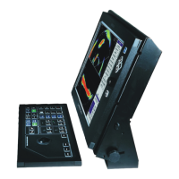
aSlidethesupportstraight"up"ontothemountingblock(B)asindicatedby
thearrow.
bInsertthelidwiththehook(C)rst,thepressitrmlyin.
cUsethehexkeytoinsertthescrewintheassignedhole(A).
6Connectthecables.
Note
Whenyouconnectthecables,makesurethattheyareallproperlysecured,andable
towithstandthevibrationandmovementsofthevessel.
Relatedtopics
OperatingPaneldescription,page26
Cablelayoutandinterconnections,page159
Technicalspecications,page388
204688OperatingPaneldimensions(Mk1),page413
440698OperatingPanelcut-outdrawing(Mk2),page415
443179OperatingPaneldimensions(Mk2),page416
439594OperatingPaneladapterplate(Mk2),page419
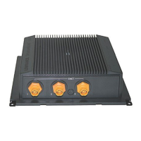
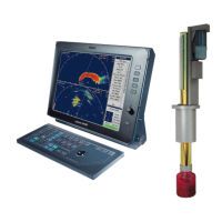
InstallingtheTransceiverUnit
Topics
TransceiverUnitinstallationprocedure,page153
Locationofthemountingbrackets,page156
Installationofthemountingbrackets,page157
ConnectingtheTransceiverUnittovesselground,page158
TransceiverUnitinstallationprocedure
TheST90TransceiverUnitisnormallypositionedinadedicatedroominthevicinity
ofthetransducer.Thephysicallengthofthecableslimitthedistancebetweenthe
transducerandtheTransceiverUnit.
Prerequisites
Youmustbeequippedwithastandardsetoftools.Thistoolsetmustcomprisethe
normaltoolsforelectronicandelectromechanicaltasks.Thisincludesdifferent
screwdrivertypes,pliers,spanners,acablestripper,asolderingiron,etc.Eachtoolmust
beprovidedinvarioussizes.Werecommendthatalltoolsaredemagnetizedtoprotect
InstallingtheST90hardwareunits