130
442703/B
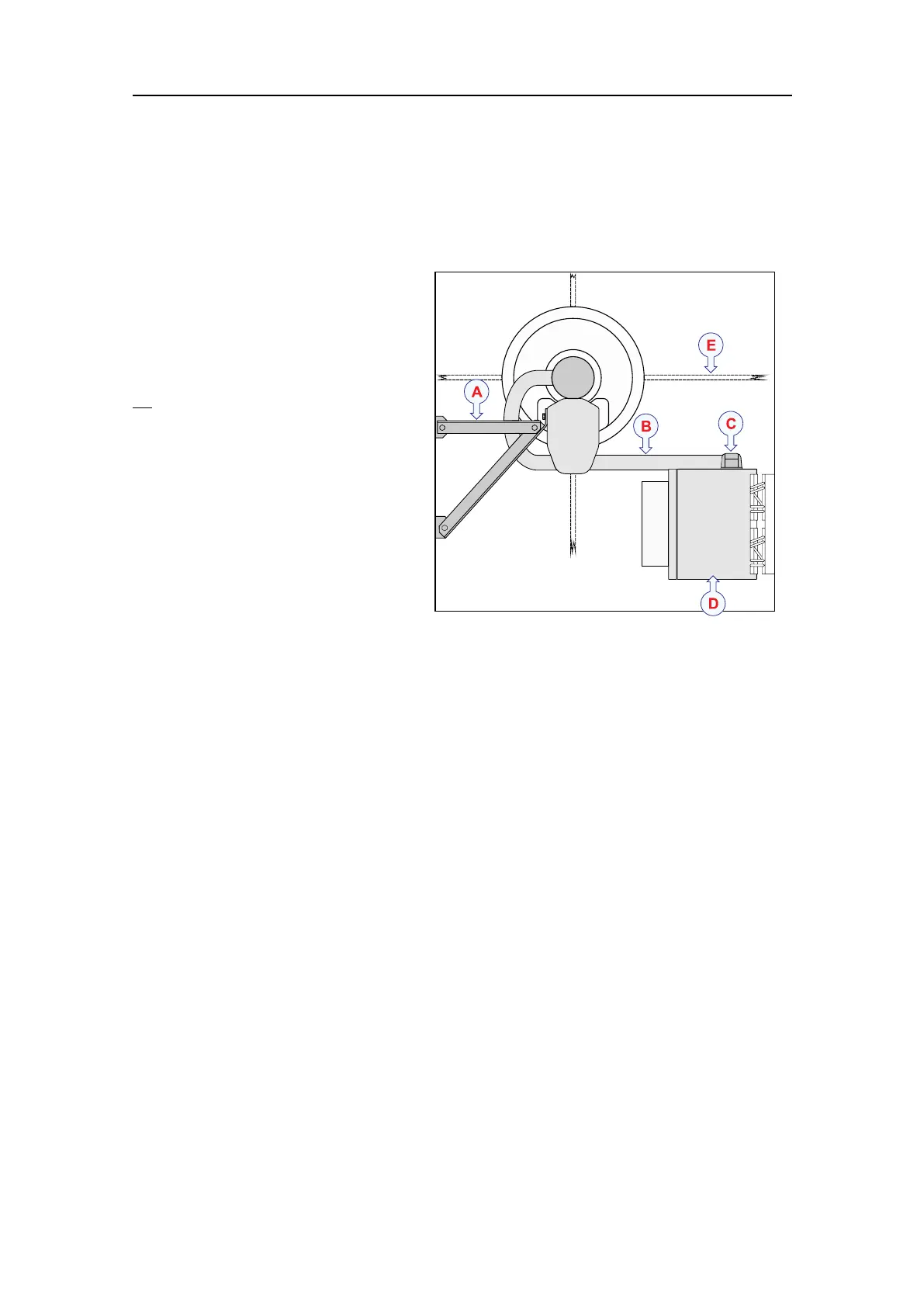
Hullunitinstallationexample:Topview
Thehullunitislocatedinthesonarroom.Thisexampleshowsatypicalsonarroom
seenfromabove.
TheST90isanomnisonar,
andthetransducercannot
bephysicallyrotated.Asa
generalrecommendation,the
hullunitshallbeorientedwith
thehoist/lowermotorpointing
aft
.Ifthisorientationmakes
itdifculttoaccesstheMotor
ControlUnit,thehullunitmay
berotatedduringitsinstallation
tothemostsuitabledirection.
AMechanicalsupport
brackets
Duetoitsheightand
weight,thehullunit
gantrymustbesecuredto
thebulkheadbymeansof
mechanicalsupportbrackets.Thedimensionsandstrengthofthesupportbrackets
mustbeadequatetopreventvortexinducedvibration.Thisarequirementtoensure
thesafetyoftheST90andthevessel.
Ifthehullunitisplacedonatransducerdockandagatevalve,additionalsupport
bracketsmustbeinstalledfromthetopofthemountingangetothebulkhead.
BTransducercable
CTransducerconnector
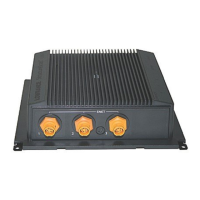
DTransceiverUnit
EThelocationoffourknee-plates(stiffeners)ontheinstallationtrunkisindicated.
Stiffentheinstallationtrunkinboththefore-and-aftandathwartshipdirections
byweldingstrengtheningknee-platesbothtothetrunkandtothedoublingplate.
Theshapeandlocationsoftheknee-platesmustbedeterminedbytheinstallation
shipyardbasedonthephysicalpropertiesofthehullandthespaceavailable.The
platesmustbeatleast1.5timesasthickasthesurroundingshellplating.
Relatedtopics
Installingthehullunit,page124
Hullunitinstallationoverview,page125
SimradST90InstallationManual