UM0306 DMA controller (DMA)
109/519
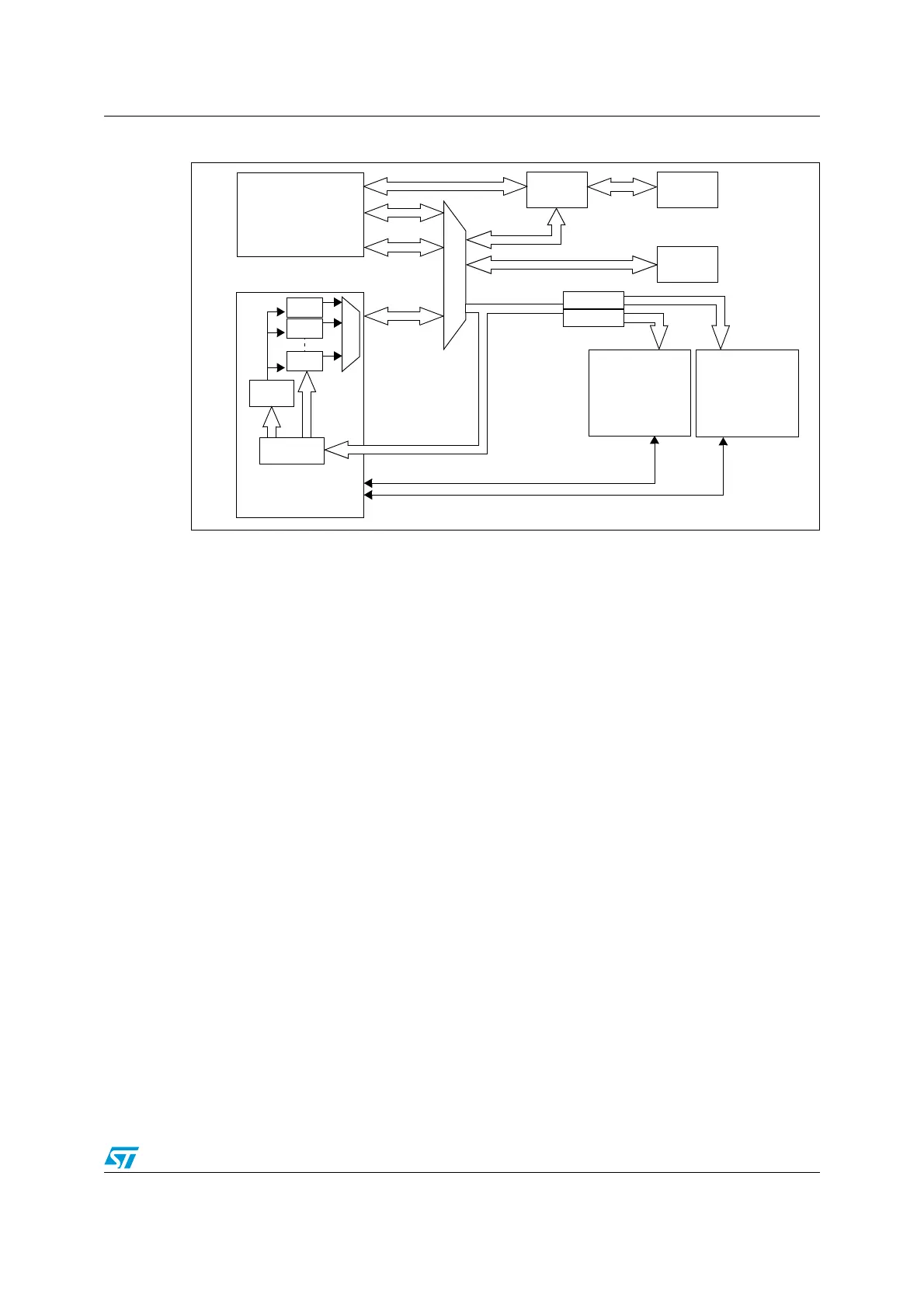
Figure 16. DMA block diagram
7.3 Functional description
The DMA controller performs direct memory transfer sharing the system bus with the
Cortex-M3 core. Thus, 1 DMA request stops the CPU accessing the system bus for at least
2 cycles. To guarantee a minimum bandwidth to the Cortex-M3 core the code execution, the
DMA controller always releases the system bus for at least one cycle between two
consecutive DMA requests.
7.3.1 DMA transactions
After an event, the peripheral sends a request signal to the DMA Controller. The DMA
controller serves the request depending on the channel priorities. As soon as the DMA
Controller accesses the peripheral, an Acknowledge is sent to the peripheral by the DMA
Controller. The peripheral releases its request as soon as it gets the Acknowledge from the
DMA Controller. Once the request is deasserted by the peripheral, the DMA Controller
release the Acknowledge. If there are more requests, the peripheral can initiate the next
transaction.
In summary, each DMA transfer consists of three operations:
● A load from the peripheral data register or a location in memory addressed through the
DMA_CMARx register
● A store of the data loaded to the peripheral data register or a location in memory
addressed through the DMA_CMARx register
● A post-decrement of the DMA_CNDTRx register, which contains the number of
transactions that have still to be performed.
FLITF
Ch.1
Ch.2
Ch.7
Arbiter
Cortex-M3
SRAM
AHB Slave
DMA
ICode
DCode
System
AHB System Bus
DMA Request
APB2 APB1
Flash
Bridge 1
Bridge 2
USART1
SPI1
ADC1
TIM1
USART2
USART3
SPI2
I2C1
I2C2
TIM2
TIM3
TIM4
 Loading...


