Memory and bus architecture UM0306
24/519
2 Memory and bus architecture
2.1 System architecture
The main system consists of:
● Four masters:
– Cortex-M3 core ICode bus (I-bus), DCode bus (D-bus), and System bus (S-bus)
– GP-DMA (General Purpose DMA)
● Three slaves:
– Internal SRAM
– Internal Flash memory
– AHB to APB bridges (AHB2APBx) which connect all the APB peripherals
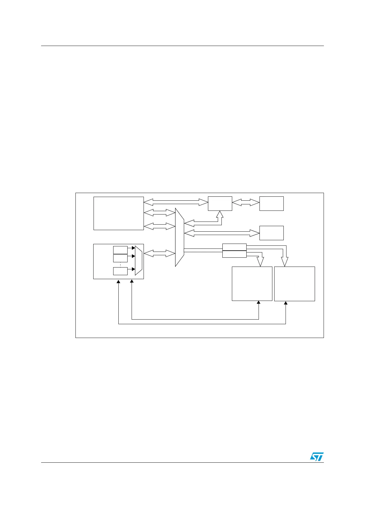
These are interconnected using a Multi-Layer AHB bus architecture as shown in Figure 1:
Figure 1. System architecture
ICode bus
This bus connects the Instruction bus of the Cortex-M3 core to the Flash memory instruction
interface. Prefetching is performed on this bus.
DCode bus
This bus connects the DCode bus (literal load and debug access) of the Cortex-M3 core to
the Flash memory Data interface.
System bus
This bus connects the system bus of the Cortex-M3 core (peripherals bus) to a BusMatrix
which manages the arbitration between the core and the DMA.
FLITF
Ch.1
Ch.2
Ch.7
Cortex-M3
SRAM
DMA
ICode
DCode
System
AHB System Bus
DMA Request
APB2 APB1
USART1
SPI1
ADC1
TIM1
USART2
USART3
SPI2
I2C1
I2C2
USB
TIM2
TIM3
TIM4
GPIOA
GPIOB
GPIOC
GPIOD
GPIOE
AFIO
WWDG
CAN
BKP
PWR
Flash
Bridge 1
Bridge 2
ADC2
IWDG
EXTI
memory
 Loading...


