UM0306 Universal synchronous asynchronous receiver transmitter (USART)
405/519
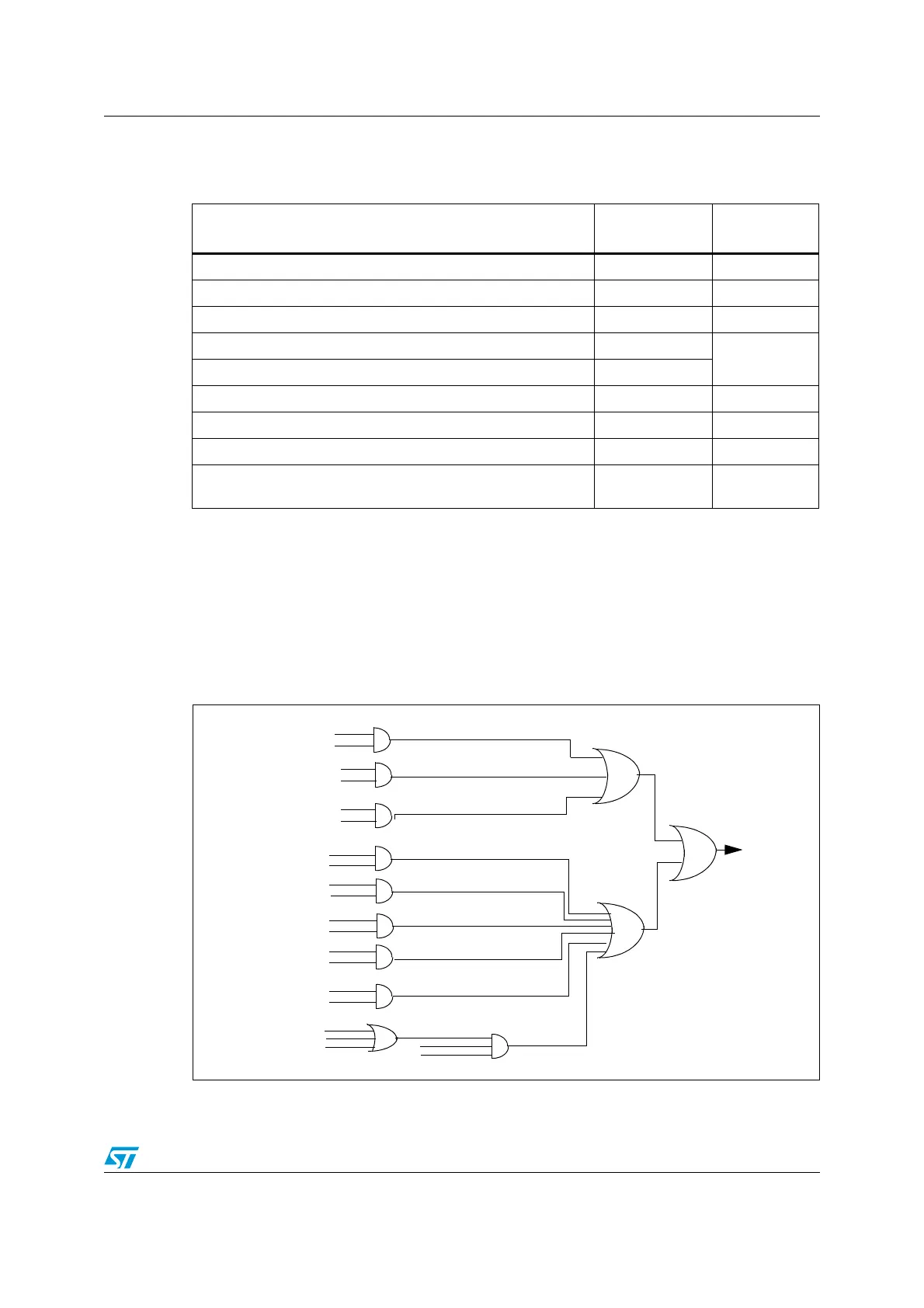
17.3 Interrupt requests
The USART interrupt events are connected to the same interrupt vector (see Figure 163).
● During transmission: Transmission Complete, Clear to Send or Transmit Data Register
empty interrupt.
● While receiving: Idle Line detection, Overrun error, Receive Data register not empty,
Parity error, LIN break detection, Noise Flag (only in multi buffer communication) and
Framing Error (only in multi buffer communication).
These events generate an interrupt if the corresponding Enable Control Bit is set.
Figure 163. USART interrupt mapping diagram
Table 53. USART interrupt requests
Interrupt Event
Event
Flag
Enable
Control Bit
Transmit Data Register Empty TXE TXEIE
CTS flag CTS CTSIE
Transmission Complete TC TCIE
Received Data Ready to be Read RXNE
RXNEIE
Overrun Error Detected ORE
Idle Line Detected IDLE IDLEIE
Parity Error PE PEIE
Break Flag LBD LBDIE
Noise Flag, Overrun error and Framing Error in multi-buffer
communication
NE or ORE or FE EIE
TC
TCIE
TXE
TXEIE
IDLE
IDLEIE
RXNEIE
ORE
RXNEIE
RXNE
PE
PEIE
FE
NE
OVR
EIE
DMAR
USART
LBD
LBDIE
CTS
CTSIE
interrupt
 Loading...


