Universal synchronous asynchronous receiver transmitter (USART) UM0306
392/519
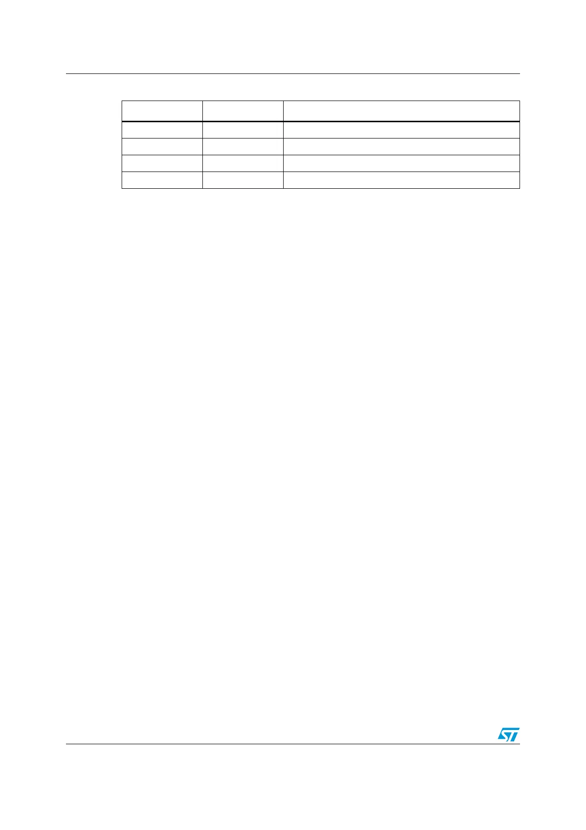
Table 52. Frame formats
Legends: SB: Start Bit, STB: Stop Bit, PB: Parity Bit
Note: In case of wake up by an address mark, the MSB bit of the data is taken into account and
not the parity bit
Even parity: the parity bit is calculated to obtain an even number of “1s” inside the frame
made of the 7 or 8 LSB bits (depending on whether M is equal to 0 or 1) and the parity bit.
Ex: data=00110101; 4 bits set => parity bit will be 0 if even parity is selected (PS bit in
USART_CR1 = 0).
Odd parity: the parity bit is calculated to obtain an odd number of “1s” inside the frame
made of the 7 or 8 LSB bits (depending on whether M is equal to 0 or 1) and the parity bit.
Ex: data=00110101; 4 bits set => parity bit will be 1 if odd parity is selected (PS bit in
USART_CR1 = 1).
Transmission mode: If the PCE bit is set in USART_CR1, then the MSB bit of the data
written in the data register is transmitted but is changed by the parity bit (even number of
“1s” if even parity is selected (PS=0) or an odd number of “1s” if odd parity is selected
(PS=1)). If the parity check fails, the PE flag is set in the USART_SR register and an
interrupt is generated if PEIE is set in the USART_CR1 register.
17.2.8 LIN (local interconnection network) mode
The LIN mode is selected by setting the LINEN bit in the USART_CR2 register. In LIN mode,
the following bits must be kept cleared:
● CLKEN in the USART_CR2 register,
● STOP[1:0], SCEN, HDSEL and IREN in the USART_CR3 register.
LIN transmission
The same procedure explained in Section 17.2.3 has to be applied for LIN Master
transmission than for normal USART transmission with the following differences:
● Clear the M bit to configure 8-bit word length.
● Set the LINEN bit to enter LIN mode. In this case, setting the SBK bit sends 13 ‘0’ bits
as a break character. Then a bit of value ‘1’ is sent to allow the next start detection.
LIN reception
When the LIN mode is enabled, the break detection circuit is activated. The detection is
totally independent from the normal USART receiver. A break can be detected whenever it
occurs, during idle state or during a frame.
When the receiver is enabled (RE=1 in USART_CR1), the circuit looks at the RX input for a
start signal. The method for detecting start bits is the same when searching break
M bit PCE bit USART frame
0 0 | SB | 8 bit data | STB |
0 1 | SB | 7-bit data | PB | STB |
1 0 | SB | 9-bit data | STB |
1 1 | SB | 8-bit data PB | STB |
 Loading...


