UM0306 General purpose timer (TIMx)
233/519
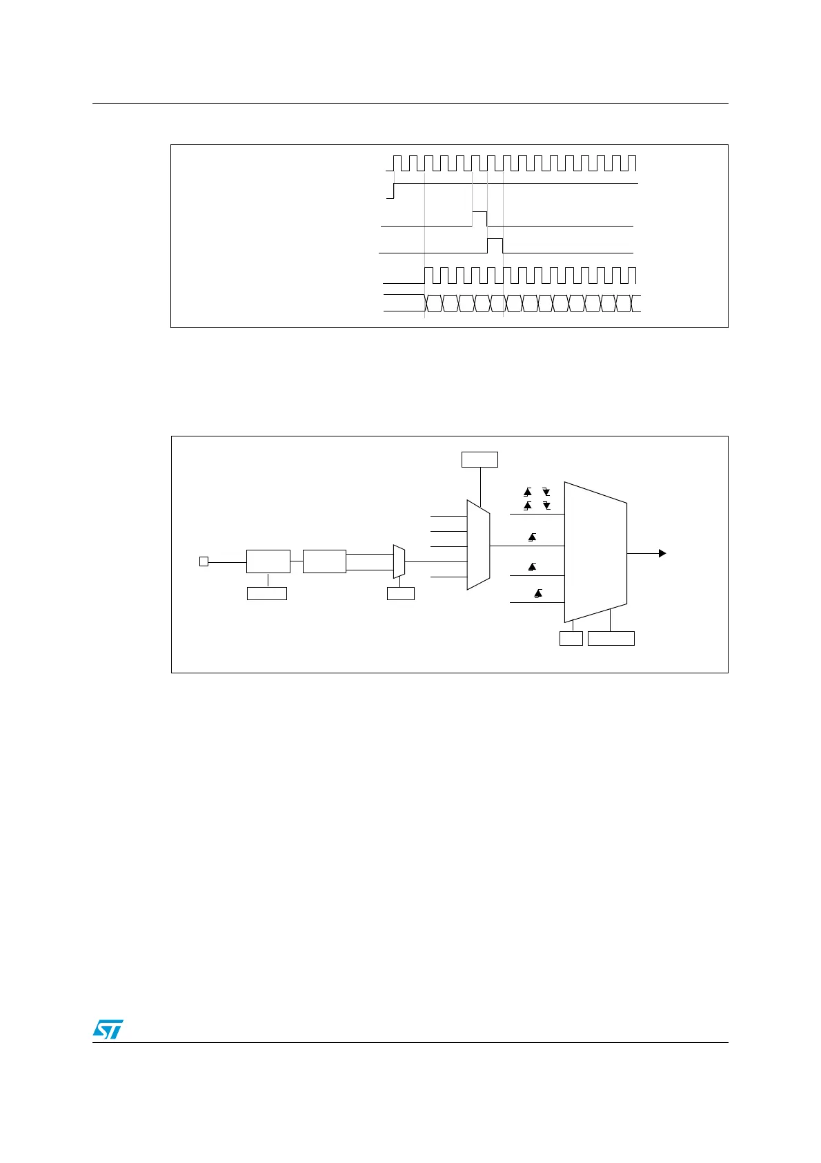
Figure 92. Control circuit in normal mode, internal clock divided by 1
External clock source mode 1
This mode is selected when SMS=111 in the TIMx_SMCR register. The counter can count
at each rising or falling edge on a selected input.
Figure 93. TI2 external clock connection example
For example, to configure the up-counter to count in response to a rising edge on the TI2
input, use the following procedure:
For example, to configure the up-counter to count in response to a rising edge on the TI2
input, use the following procedure:
1. Configure channel 2 to detect rising edges on the TI2 input by writing CC2S= ‘01’ in the
TIMx_CCMR1 register.
2. Configure the input filter duration by writing the IC2F[3:0] bits in the TIMx_CCMR1
register (if no filter is needed, keep IC2F=0000).
Note: The capture prescaler is not used for triggering, so you don’t need to configure it.
3. Select rising edge polarity by writing CC2P=0 in the TIMx_CCER register.
4. Configure the timer in external clock mode 1 by writing SMS=111 in the TIMx_SMCR
register.
5. Select TI2 as the input source by writing TS=110 in the TIMx_SMCR register.
6. Enable the counter by writing CEN=1 in the TIMx_CR1 register.
When a rising edge occurs on TI2, the counter counts once and the TIF flag is set.
CK_INT
00
COUNTER CLOCK = CK_CNT = CK_PSC
COUNTER REGISTER
01 02 03 04 05 06 0732 33 34 35 3631
CEN=CNT_EN
UG
CNT_INIT
CK_INT
encoder
mode
external clock
mode 1
external clock
mode 2
internal clock
mode
etrf
trgi
ti1f
ti2f
or
or
or
(internal clock)
CK_PSC
ECE
TIMx_SMCR
SMS[2:0]
ITR1
ti1f_ed
ti1fp1
ti2fp2
etrf
TIMx_SMCR
TS[2:0]
TI2
0
1
TIMx_CCER
CC2P
Filter
ICF[3:0]
TIMx_CCMR1
Edge
Detector
ti2f_rising
ti2f_falling
110
001
100
101
111
 Loading...


