Universal synchronous asynchronous receiver transmitter (USART) UM0306
390/519
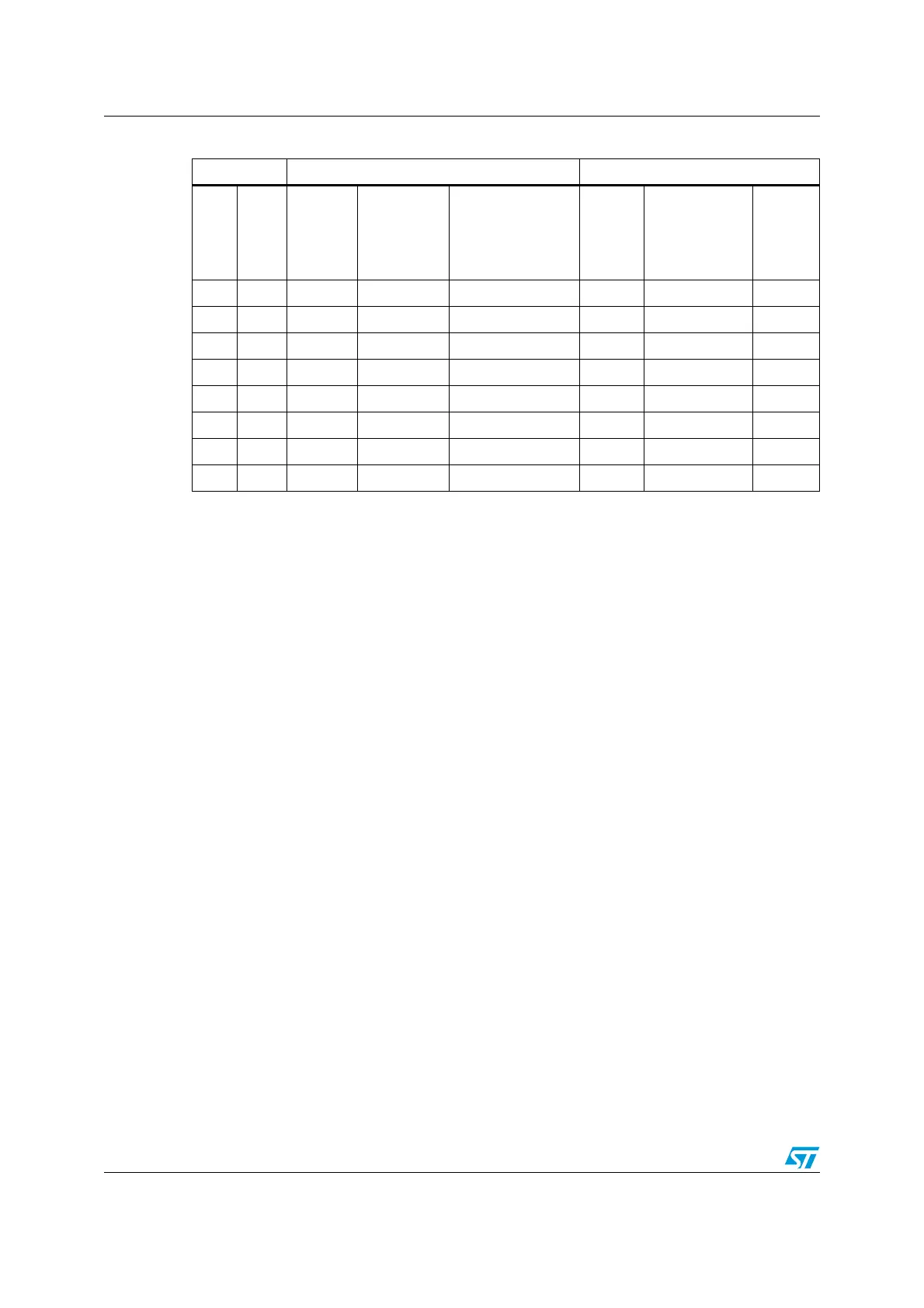
Table 51. Error Calculation for Programmed Baud Rates
Note: The lower the CPU clock the lower will be the accuracy for a particular Baud rate. The upper
limit of the achievable baud rate can be fixed with this data.
17.2.6 Multi-processor communication
There is a possibility of performing multi-processor communication with the USART (several
USARTs connected in a network). For instance one of the USARTs can be the master, its
TX output is connected to the RX input of the other USART. The others are slaves, their
respective TX outputs are logically ANDed together and connected to the RX input of the
master.
In multi-processor configurations it is often desirable that only the intended message
recipient should actively receive the full message contents, thus reducing redundant USART
service overhead for all non addressed receivers.
The non addressed devices may be placed in mute mode by means of the muting function.
In mute mode:
● None of the reception status bits can be set.
● All the receive interrupts are inhibited.
● The RWU bit in USART_CR1 register is set to 1. RWU can be controlled automatically
by hardware or written by the software under certain conditions.
The USART can enter or exit from mute mode using one of two methods, depending on the
WAKE bit in the USART_CR1 register:
● Idle Line detection if the WAKE bit is reset,
● Address Mark detection if the WAKE bit is set.
Idle line detection (WAKE=0)
The USART enters mute mode when the RWU bit is written to 1.
It wakes up when an Idle frame is detected. Then the RWU bit is cleared by hardware but
the IDLE bit is not set in the USART_SR register. RWU can also be written to 0 by software.
An example of mute mode behavior using idle line detection is given in Figure 148.
Baud Rate f
CPU
= 10 Mhz f
CPU
= 40 MHz
S.No
in
Kbps
Actual
Value
programmed
in the Baud
Rate
Register
% Error
=(Calculated -
Desired)B.Rate
/Desired B.Rate
Actual
Value
programmed in
the Baud Rate
Register
% Error
1. 2.4 2.399 260.4375 -0.04% 2.3999 1041.6875 0.04%
2. 9.6 9.596 65.125 -0.04% 9.599 260.4375 -0.01%
3. 19.2 19.193 32.5625 -0.03% 19.203 130.1875 -0.02%
4. 57.6 57.471 10.875 -0.22% 57.637 43.375 0.06%
5. 115.2 114.942 5.4375 -0.22% 115.274 21.6875 0.06%
6. 230.4 232.558 2.6875 -0.94% 229.885 10.875 -0.22%
7. 460.8 454.545 1.375 -1.36% 459.77 5.4375 -0.22%
8. 921.6 NA NA NA 930.232 2.6875 0.94%
 Loading...


