Advanced control timer (TIM1) UM0306
154/519
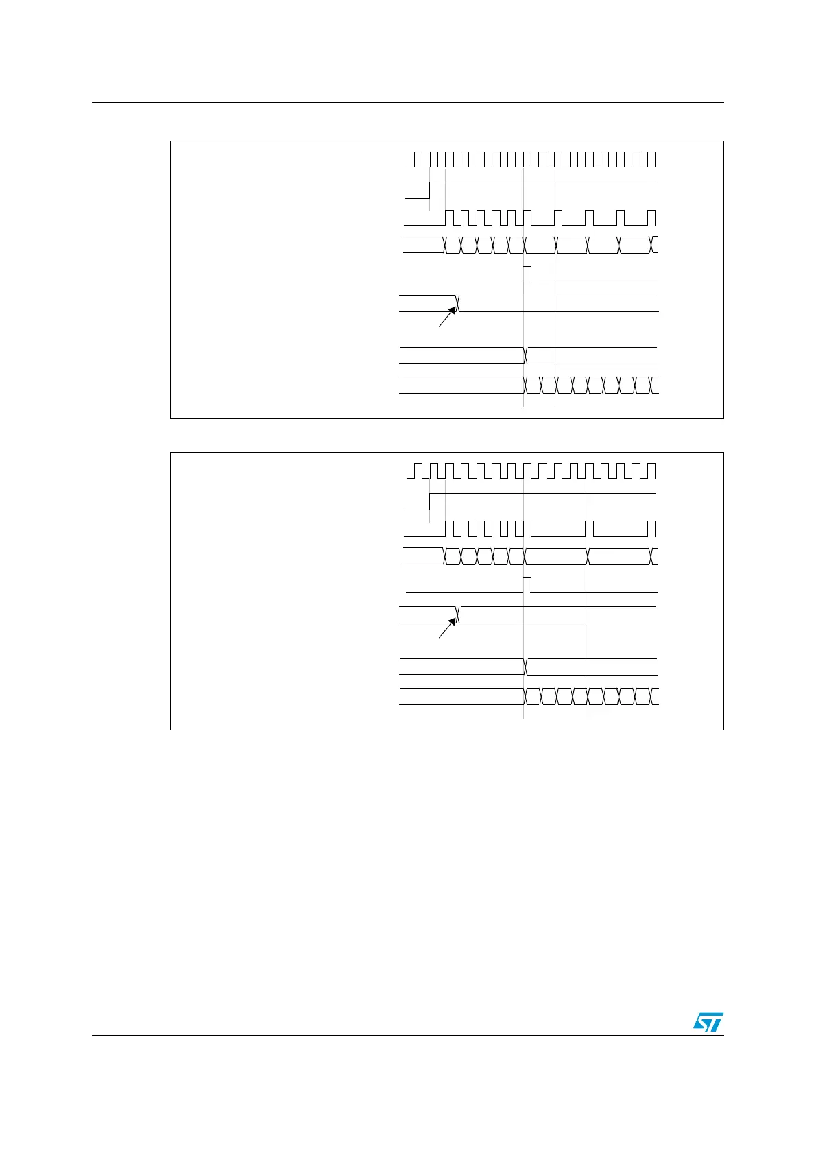
Figure 25. Counter timing diagram with prescaler division change from 1 to 2
Figure 26. Counter timing diagram with prescaler division change from 1 to 4
12.4.2 Counter modes
Up-counting mode
In up-counting mode, the counter counts from 0 to the auto-reload value (content of the
TIM1_ARR register), then restarts from 0 and generates a counter overflow event.
If the repetition counter is used, the update event (UEV) is generated after up-counting is
repeated for the number of times programmed in the repetition counter register
(TIM1_RCR). Else the update event is generated at each counter overflow.
Setting the UG bit in the TIM1_EGR register (by software or by using the slave mode
controller) also generates an update event.
The UEV event can be disabled by software by setting the UDIS bit in the TIM1_CR1
register. This is to avoid updating the shadow registers while writing new values in the
CK_PSC
00
CNT_EN
TIMER CLOCK = CK_CNT
COUNTER REGISTER
UPDATE EVENT (UEV)
0
F9 FA FB FCF7
PRESCALER CONTROL REGISTER
01
Write a new value in TIM1_PSC
01 02 03
PRESCALER BUFFER
01
PRESCALER COUNTER
0
1 0 1 0 1 0 1
F8
CK_PSC
00
CNT_EN
TIMER CLOCK = CK_CNT
COUNTER REGISTER
UPDATE EVENT (UEV)
0
F9 FA FB FCF7
PRESCALER CONTROL REGISTER
03
Write a new value in TIM1_PSC
PRESCALER BUFFER
03
PRESCALER COUNTER
0
1 2 3 0 1 2 3
F8 01
 Loading...


