UM0306 Universal synchronous asynchronous receiver transmitter (USART)
391/519
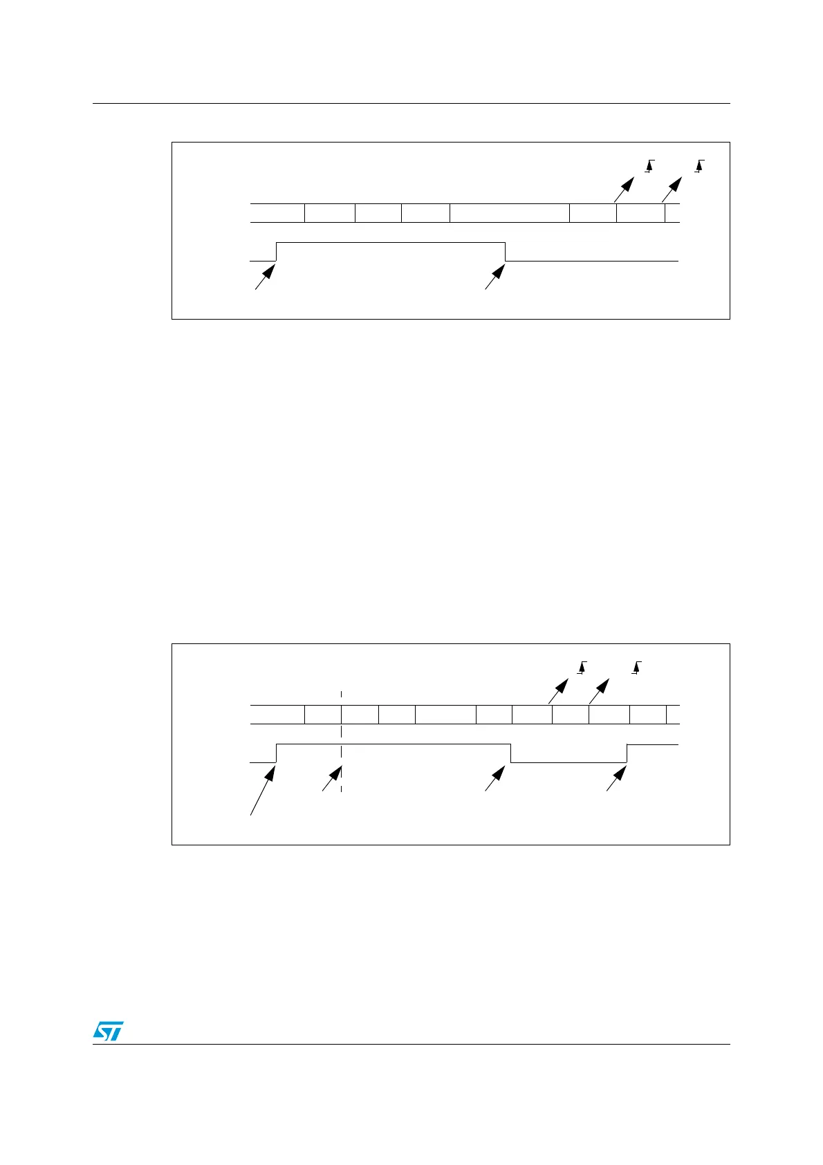
Figure 148. Mute mode using Idle line detection
Address mark detection (WAKE=1)
In this mode, bytes are recognized as addresses if their MSB is a ‘1’ else they are
considered as data. In an address byte, the address of the targeted receiver is put on the 4
LSB. This 4-bit word is compared by the receiver with its own address which is programmed
in the ADD bits in the USART_CR2 register.
The USART enters mute mode when an address character is received which does not
match its programmed address. The RXNE flag is not set for this address byte and no
interrupt nor DMA request is issued as the USART would have entered mute mode.
It exits from mute mode when an address character is received which matches the
programmed address. Then the RWU bit is cleared and subsequent bytes are received
normally. The RXNE bit is set for the address character since the RWU bit has been cleared.
The RWU bit can be written to as 0 or 1 when the receiver buffer contains no data (RXNE=0
in the USART_SR register). Otherwise the write attempt is ignored.
An example of mute mode behavior using address mark detection is given in Figure 149.
Figure 149. Mute mode using Address mark detection
17.2.7 Parity control
Parity control (generation of parity bit in transmission and parity checking in reception) can
be enabled by setting the PCE bit in the USART_CR1 register. Depending on the frame
length defined by the M bit, the possible USART frame formats are as listed in Table 52.
RWU written to 1
Data 1 IDLE
RX
Data 2 Data 3 Data 4 Data 6Data 5
RWU
Mute Mode Normal Mode
Idle frame detected
RXNE RXNE
RWU written to 1
IDLE
RX
Addr=0
RWU
Mute Mode Normal Mode
Matching address
RXNE RXNE
(RXNE was cleared)
Data 2 Data 3 Data 4 Data 5Data 1 IDLE Addr=1 Addr=2
Mute Mode
In this example, the current address of the receiver is 1
(programmed in the USART_CR2 register)
Non-matching address
Non-matching address
 Loading...


