UM0306 Advanced control timer (TIM1)
159/519
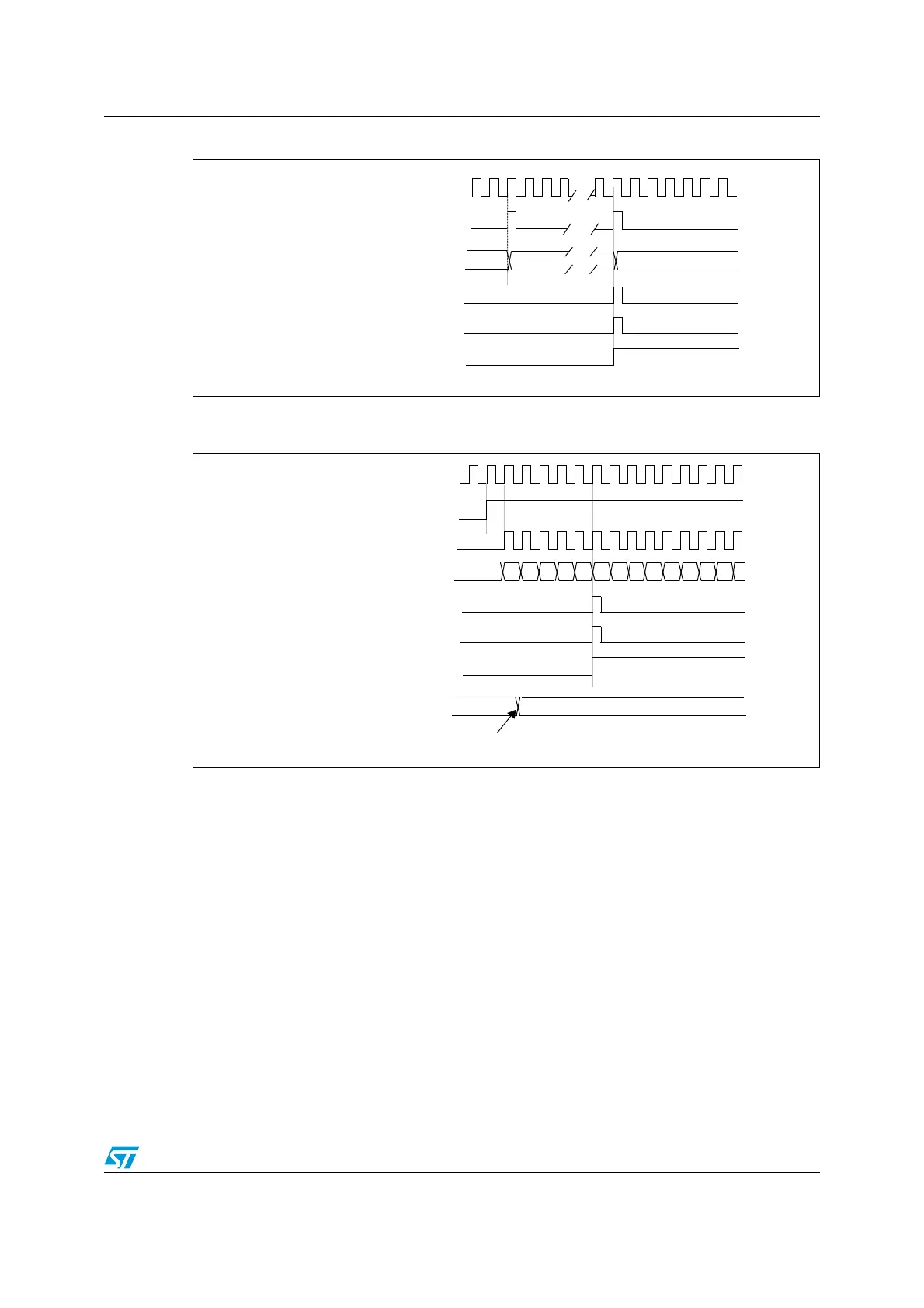
Figure 36. Counter timing diagram, internal clock divided by N
Figure 37. Counter timing diagram, Update event when repetition counter is not
used
Center-aligned mode (up/down counting)
In center-aligned mode, the counter counts from 0 to the auto-reload value (content of the
TIM1_ARR register), generates an counter overflow event, then counts down to 0 and
generates a counter underflow event. Then it restarts counting from 0.
In this mode, the DIR direction bit in the TIM1_CR1 register cannot be written. It is updated
by hardware and gives the current direction of the counter.
The update event can be generated at each counter overflow and at each counter underflow
or by setting the UG bit in the TIM1_EGR register (by software or by using the slave mode
controller) also generates an update event. In this case, the counter restarts counting from
0, as well as the counter of the prescaler.
The UEV update event can be disabled by software by setting the UDIS bit in the TIM1_CR1
register. This is to avoid updating the shadow registers while writing new values in the
preload registers. Then no update event occurs until UDIS bit has been written to 0.
However, the counter continues counting up and down, based on the current auto-reload
value.
TIMER CLOCK = CK_CNT
COUNTER REGISTER
36
20
1F
UPDATE INTERRUPT FLAG (UIF)
COUNTER UNDERFLOW
UPDATE EVENT (UEV)
CK_PSC
00
CK_PSC
36
CNT_EN
TIMER CLOCK = CK_CNT
COUNTER REGISTER
UPDATE INTERRUPT FLAG (UIF)
COUNTER UNDERFLOW
UPDATE EVENT (UEV)
35 34 33 32 31 30 2F04 03 02 01 0005
AUTO-RELOAD REGISTER
FF 36
Write a new value in TIM1_ARR
 Loading...


