Real-Time Clock (RTC) UM0306
124/519
8.3.4 Configuring RTC registers
To write in the RTC_PRL, RTC_CNT, RTC_ALR registers, the peripheral must enter
Configuration Mode. This is done by setting the CNF bit in the RTC_CRL register.
In addition, writing to any RTC register is only enabled if the previous write operation is
finished. To enable the software to detect this situation, the RTOFF status bit is provided in
the RTC_CR register to indicate that an update of the registers is in progress. A new value
can be written to the RTC registers only when the RTOFF status bit value is ’1’.
Configuration procedure:
1. Poll RTOFF, wait until its value goes to ‘1’
2. Set the CNF bit to enter configuration mode
3. Write to one or more RTC registers
4. Clear the CNF bit to exit configuration mode
5. Poll RTOFF, wait until its value goes to ‘1’ to check the end of the write operation.
The write operation only executes when the CNF bit is cleared; it takes at least three
RTCCLK cycles to complete.
8.3.5 Asserting RTC flags
The RTC Second flag (SECF) is asserted on each RTC Core clock cycle before the update
of the RTC Counter.
The RTC Overflow flag (OWF) is asserted on the last RTC Core clock cycle before the
counter reaches 0x0000.
The RTC_Alarm and RTC Alarm flag (ALRF) (see Figure 19) are asserted on the last RTC
Core clock cycle before the counter reaches the RTC Alarm value stored in the Alarm
register increased by one (RTC_ALR + 1). The write operation in the RTC Alarm and RTC
Second flag must be synchronized by using one of the following sequences:
● Use the RTC Alarm interrupt and inside the RTC interrupt routine, the RTC Alarm
and/or RTC Counter registers are updated.
● Wait for SECF bit to be set in the RTC Control register. Update the RTC Alarm and/or
the RTC Counter register.
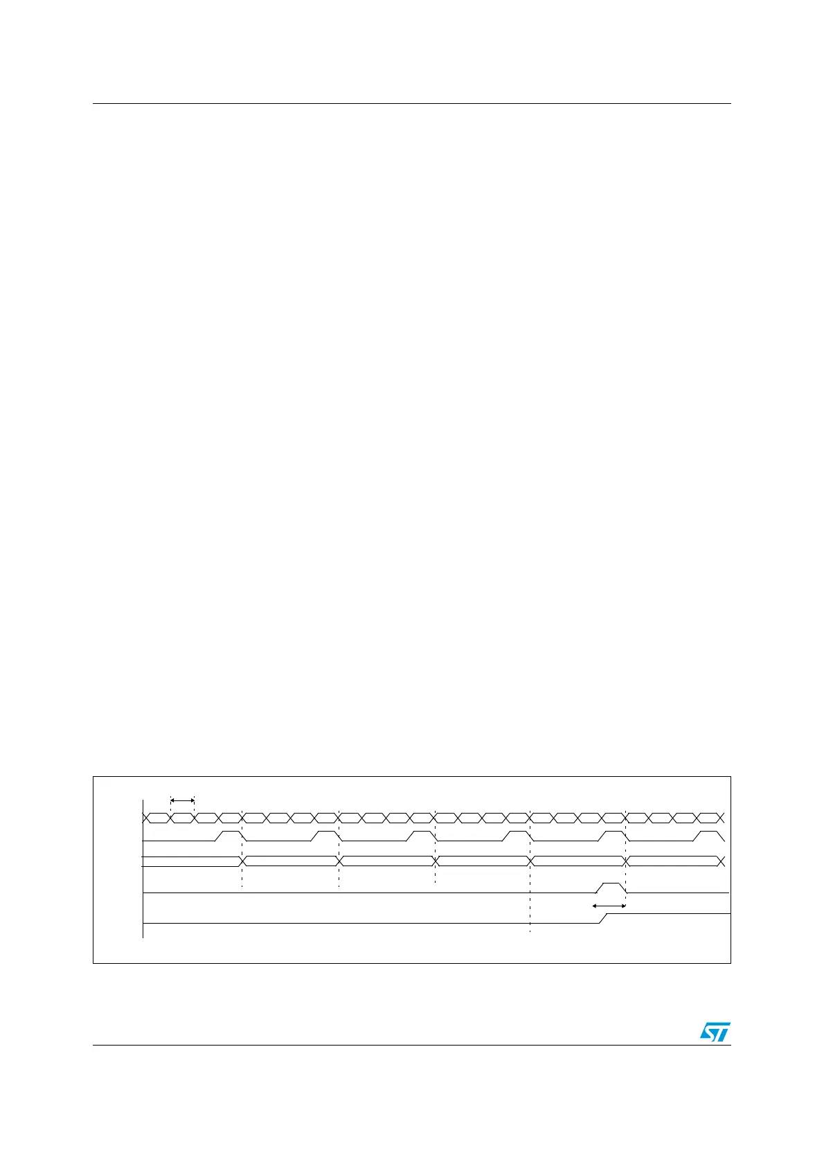
Figure 19. RTC second and alarm waveform example with PR=0003, ALARM=00004
RTC_CNT 0000
0001
RTC_PR
0002 0001 0000 0003 0002 0001 0000 0003
0002
RTC_ALARM
0002 0001 0000 0003
0003
0002 0001 0000 0003
0004
0002 0001 0000 0003
ALRF
can be cleared by software
RTC_Second
RTCCLK
0005
0002 0001 0000 0003
(not powered
in STANDBY)
1 RTCCLK
 Loading...


