Controller area network (bxCAN) UM0306
292/519
identifiers. All bits of the incoming identifier must match the bits specified in the filter
registers.
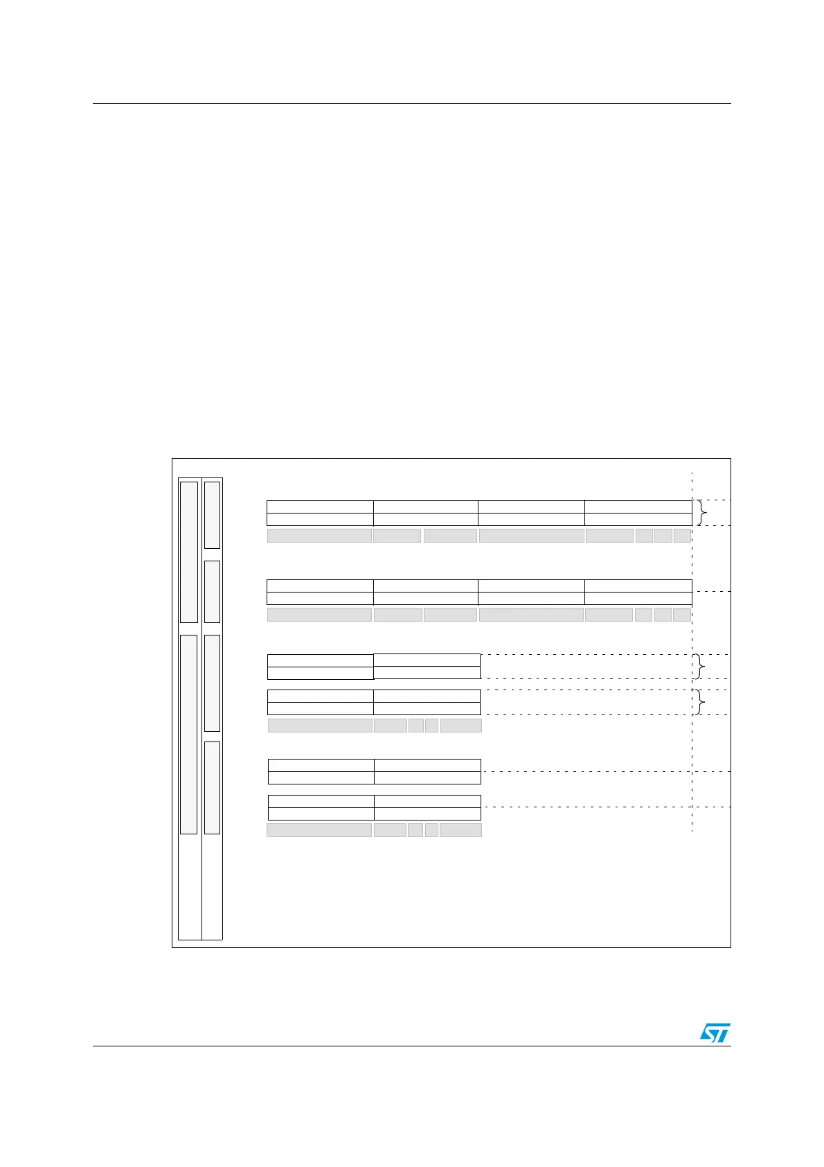
Filter bank scale and mode configuration
The filter banks are configured by means of the corresponding CFMR register. To configure
a filter bank it must be deactivated by clearing the FACT bit in the CAN_FAR register. The
filter scale is configured by means of the corresponding FSCx bit in the CFSCR register,
refer to Figure 126. The identifier list or identifier mask mode for the corresponding
Mask/Identifier registers is configured by means of the FBMx bits in the CFMR register.
To filter a group of identifiers, configure the Mask/Identifier registers in mask mode.
To select single identifiers, configure the Mask/Identifier registers in identifier list mode.
Filters not used by the application should be left deactivated.
Each filter within a filter bank is numbered (called the Filter Number) from 0 to a maximum
dependent on the mode and the scale of each of the 14 filter banks.
Concerning the filter configuration, refer to Figure 126.
Figure 126. Filter bank scale configuration - register organization
One 32-Bit Filter - Identifier Mask
Two 16-Bit Filters - Identifier Mask
CAN_FxR0[31:24]
CAN_FxR1[31:24]
CAN_FxR0[15:8]
CAN_FxR0[31:24]
CAN_FxR0[7:0]
CAN_FxR0[23:16]
x = filter bank number
FSCx = 1FSCx = 0
1
These bits are located in the CAN_FS0R register
Filter Bank Scale
ID
Mask
ID
Mask
STID[10:3]
STID[2:0]
EXID[12:5]
Mapping
STID[10:3]
ID
Mask
Mapping
RTR
Two 32-Bit Filters - Identifier List
ID
ID
STID[10:3] STID[2:0] EXID[12:5]
Mapping
Four 16-Bit Filters - Identifier List
ID
ID
STID[10:3]
ID
ID
Mapping
n
n+1
n+2
n+3
n+1
Filter Bank Mode
2
n
n
n+1
EXID[4:0] IDE
EXID[17:13]
EXID[17:13]
STID[2:0] RTR IDE EXID[17:15]
FBMx = 0FBMx = 1
Filter
2
These bits are located in the CAN_FM0R register
n
Num.
FBMx = 0FBMx = 1
Config. Bits
1
STID[2:0] RTR IDE EXID[17:15]
0
RTREXID[4:0] IDE 0
CAN_FxR0[23:16] CAN_FxR0[15:8] CAN_FxR0[7:0]
CAN_FxR1[7:0]CAN_FxR1[15:8]CAN_FxR1[23:16]
CAN_FxR0[31:24]
CAN_FxR1[31:24]
CAN_FxR0[23:16] CAN_FxR0[15:8] CAN_FxR0[7:0]
CAN_FxR1[7:0]CAN_FxR1[15:8]CAN_FxR1[23:16]
CAN_FxR1[15:8]
CAN_FxR1[31:24]
CAN_FxR1[7:0]
CAN_FxR1[23:16]
CAN_FxR0[15:8]
CAN_FxR0[31:24]
CAN_FxR0[7:0]
CAN_FxR0[23:16]
CAN_FxR1[15:8]
CAN_FxR1[31:24]
CAN_FxR1[7:0]
CAN_FxR1[23:16]
ID=Identifier
 Loading...


