UM0306 Analog/digital converter (ADC)
465/519
19.10.3 Fast interleaved mode
This mode can be started only on a regular channel group (usually one channel). The
source of external trigger comes from the regular channel mux of ADC1. After an external
trigger occurs:
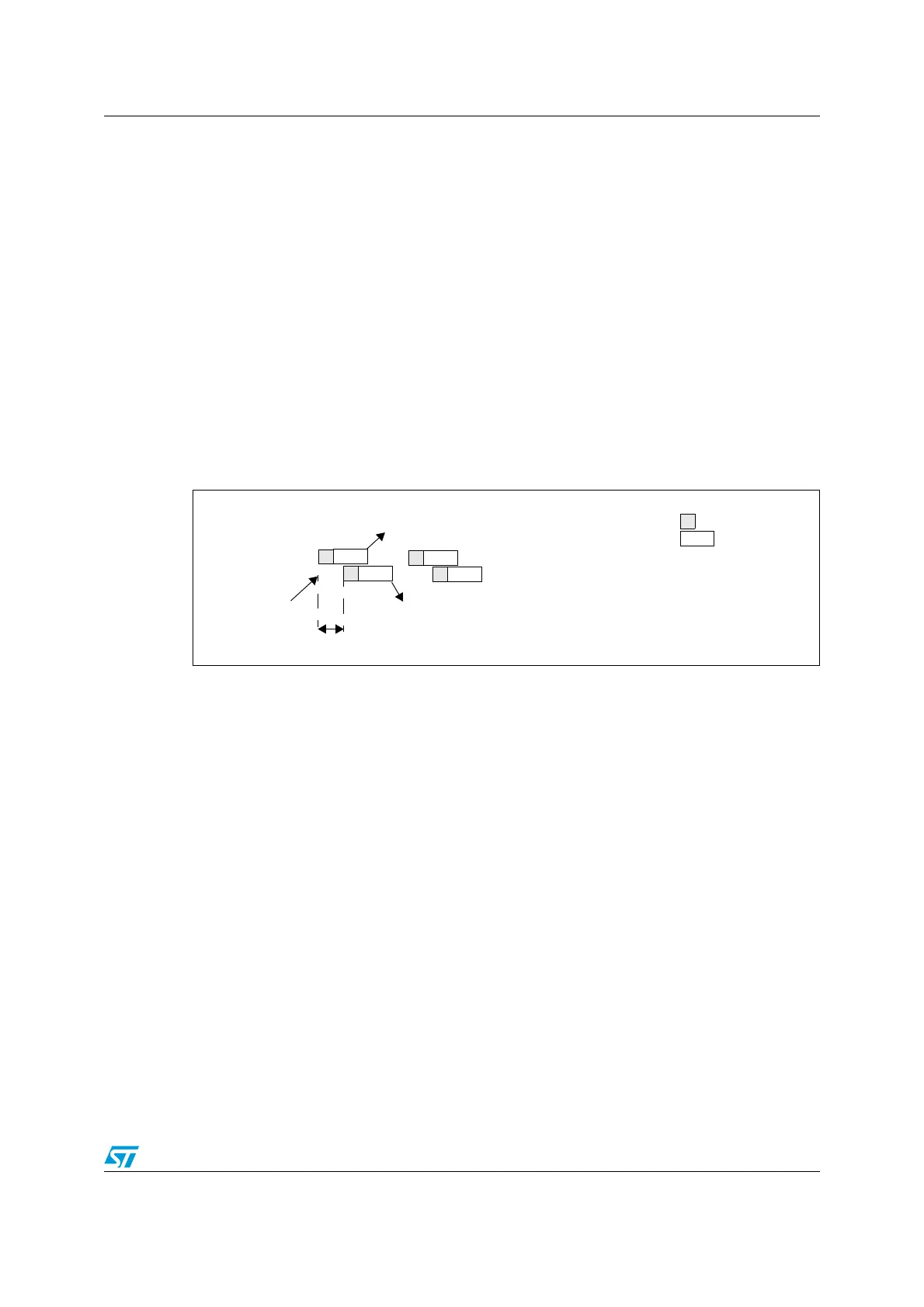
● ADC2 starts immediately and
● ADC1 starts after a delay of 7 ADC clock cycles.
If CONT bit is set on both ADC1 and ADC2 the selected regular channels of both ADCs are
continuously converted.
After an EOC interrupt is generated by ADC1 (if enabled through the EOCIE bit) a 32-bit
DMA transfer request is generated (if the DMA bit is set) which transfers to SRAM the
ADC1_DR 32-bit register containing the ADC2 converted data in the upper halfword and the
ADC1 converted data in the lower halfword.
Note: The maximum sampling time allowed is <7 ADCCLK cycles to avoid the overlap between
ADC1 and ADC2 sampling phases in the event that they convert the same channel.
Figure 176. Fast interleaved mode on 1 channel in continuous conversion mode
19.10.4 Slow interleaved mode
This mode can be started only on a regular channel group (only one channel). The source of
external trigger comes from regular channel mux of ADC1. After external trigger occurs:
● ADC2 starts immediately and
● ADC1 starts after a delay of 14 ADC clock cycles.
● ADC2 starts after a second delay of 14 ADC cycles, and so on.
Note: The maximum sampling time allowed is <14 ADCCLK cycles to avoid an overlap with the
next conversion.
After an EOC interrupt is generated by ADC1 (if enabled through the EOCIE bit) a 32-bit
DMA transfer request is generated (if the DMA bit is set) which transfers to SRAM the
ADC1_DR 32-bit register containing the ADC2 converted data in the upper halfword and the
ADC1 converted data in the lower halfword.
A new ADC2 start is automatically generated after 28 ADC clock cycles
CONT bit can not be set in the mode since it continuously converts the selected regular
channel.
Note: The application must ensure that no external trigger for injected channel occurs when
interleaved mode is enabled.
CH0
CH0
ADC2
ADC1
Trigger
End of conversion on ADC1
Conversion
Sampling
CH0
CH0
...
...
7 ADCCLK
cycles
End of conversion on ADC2
 Loading...


