Advanced control timer (TIM1) UM0306
190/519
1. Configure the external trigger input circuit by programming the TIM1_SMCR register as
follows:
– ETF = 0000: no filter
– ETPS=00: prescaler disabled
– ETP=0: detection of rising edges on ETR and ECE=1 to enable the external clock
mode 2.
2. Configure the channel 1 as follows, to detect rising edges on TI:
– IC1F=0000: no filter.
– The capture prescaler is not used for triggering and does not need to be
configured.
– CC1S=01in TIM1_CCMR1 register to select only the input capture source
– CC1P=0 in TIM1_CCER register to validate the polarity (and detect rising edge
only).
3. Configure the timer in trigger mode by writing SMS=110 in TIM1_SMCR register.
Select TI1 as the input source by writing TS=101 in TIM1_SMCR register.
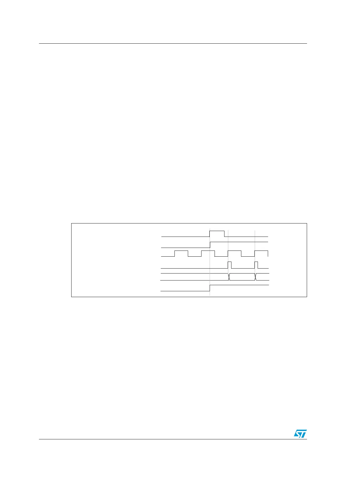
A rising edge on TI1 enables the counter and sets the TIF flag. The counter then counts on
ETR rising edges.
The delay between the rising edge of the ETR signal and the actual reset of the counter is
due to the resynchronization circuit on ETRP input.
Figure 71. Control circuit in external clock mode 2 + trigger mode
12.4.20 Timer synchronization
The TIM timers are linked together internally for timer synchronization or chaining. Refer to
Section 13.4.15: Timer synchronization on page 251 for details.
12.4.21 Debug mode
When the microcontroller enters debug mode (Cortex-M3 core halted), the TIM1 counter
either continues to work normally or stops, depending on DBG_TIM1_STOP configuration
bit in DBG module. For more details, refer to Section 20.15.2: Debug support for timers and
watchdog and bxCAN.
COUNTER CLOCK = CK_CNT = CK_PSC
COUNTER REGISTER
35 3634
ETR
CEN/CNT_EN
TIF
TI1
 Loading...


