UM0306 Controller area network (bxCAN)
283/519
application messages, Network Management and Diagnostic messages have been
introduced.
● An enhanced filtering mechanism is required to handle each type of message.
Furthermore, application tasks require more CPU time, therefore real-time constraints
caused by message reception have to be reduced.
● A receive FIFO scheme allows the CPU to be dedicated to application tasks for a long
time period without losing messages.
The standard HLP (Higher Layer Protocol) based on standard CAN drivers requires an
efficient interface to the CAN controller.
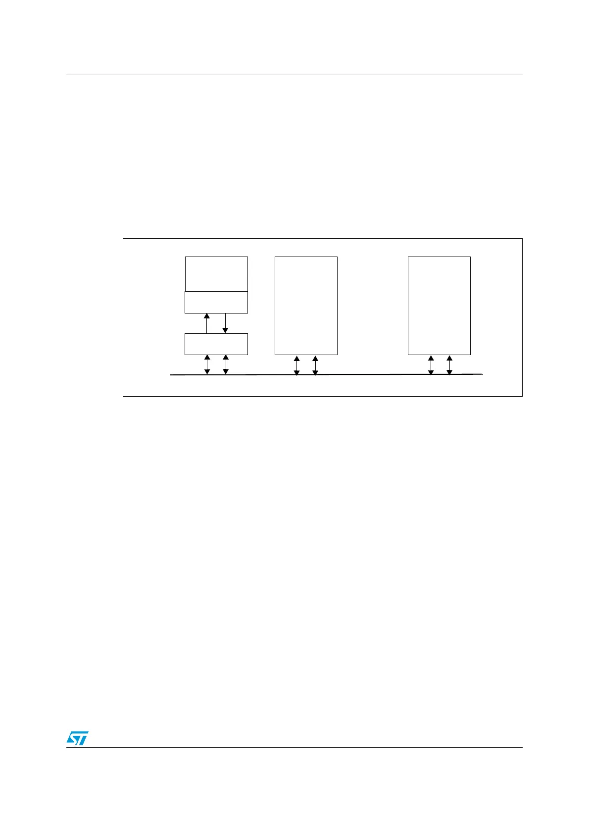
Figure 118. CAN network topology
14.3.1 CAN 2.0B active core
The bxCAN module handles the transmission and the reception of CAN messages fully
autonomously. Standard identifiers (11-bit) and extended identifiers (29-bit) are fully
supported by hardware.
14.3.2 Control, status and configuration registers
The application uses these registers to:
● Configure CAN parameters, e.g. baud rate
● Request transmissions
● Handle receptions
● Manage interrupts
● Get diagnostic information
14.3.3 Tx mailboxes
Three transmit mailboxes are provided to the software for setting up messages. The
transmission Scheduler decides which mailbox has to be transmitted first.
14.3.4 Acceptance filters
The bxCAN provides 14 scalable/configurable identifier filter banks for selecting the
incoming messages the software needs and discarding the others.
CAN node 1
CAN node 2
CAN node n
CAN
CAN
High Low
CAN
CAN
Rx
Tx
CAN
Transceiver
CAN
Controller
MCU
CAN Bus
Application
 Loading...


