UM0306 Universal synchronous asynchronous receiver transmitter (USART)
397/519
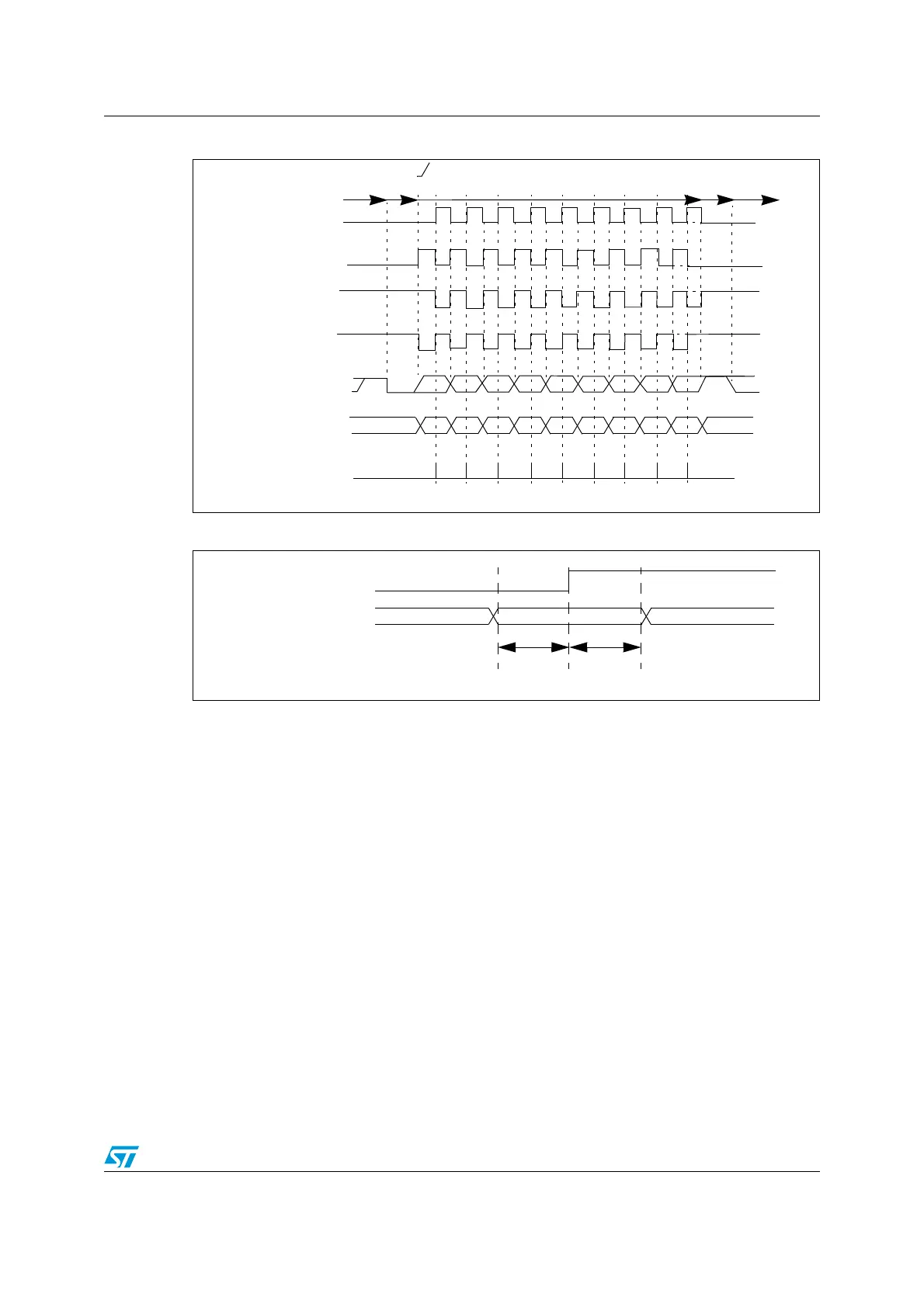
Figure 154. USART data clock timing diagram (M=1)
Figure 155. RX data setup/hold time
Note: The function of SCLK is different in Smartcard mode. Refer to the Smartcard mode chapter
for more details.
17.2.10 Single wire half duplex communication
The single-wire half-duplex mode is selected by setting the HDSEL bit in the USART_CR3
register. In this mode, the following bits must be kept cleared:
● LINEN and CLKEN bits in the USART_CR2 register,
● SCEN and IREN bits in the USART_CR3 register.
The USART can be configured to follow a single wire half duplex protocol. The selection
between half and full duplex communication is done with a control bit ‘HALF DUPLEX SEL’
(HDSEL in USART_CR3).
As soon as HDSEL is written to 1:
● RX is no longer used,
● TX is always released when no data is transmitted. Thus, it acts as a standard I/O in
idle or in reception. It means that the I/O must be configured so that TX is configured as
floating input (or output high open-drain) when not driven by the USART.
Apart from this, the communications are similar to what is done in normal USART mode.
The conflicts on the line must be managed by the software (by the use of a centralized
Idle or next
M=1 (9 data bits)
Clock (CPOL=0, CPHA=1)
Clock (CPOL=1, CPHA=0)
Clock (CPOL=1, CPHA=1)
Start LSB
MSB Stop
* LBCL bit controls last data clock pulse
Start
Idle or preceding
transmission
Data on TX
Stop
Clock (CPOL=0, CPHA=0)
01 23456 7
*
*
*
*
8
transmission
Capture Strobe
LSB
MSB
Data on RX
01 23456 7
(from slave)
(from master)
*
8
valid DATA bit
t
SETUP
t
HOLD
SCLK (capture strobe on SCLK
rising edge in this example)
Data on RX
(from slave)
t
SETUP
= t
HOLD
1/16 bit time
 Loading...


