Universal synchronous asynchronous receiver transmitter (USART) UM0306
396/519
has been written). This means that it is not possible to receive a synchronous data without
transmitting data.
2 The LBCL, CPOL and CPHA bits have to be selected when both the transmitter and the
receiver are disabled (TE=RE=0) to ensure that the clock pulses function correctly. These
bits should not be changed while the transmitter or the receiver is enabled.
3 It is advised that TE and RE are set in the same instruction in order to minimize the setup
and the hold time of the receiver.
4 The USART supports master mode only: it cannot receive or send data related to an input
clock (SCLK is always an output).
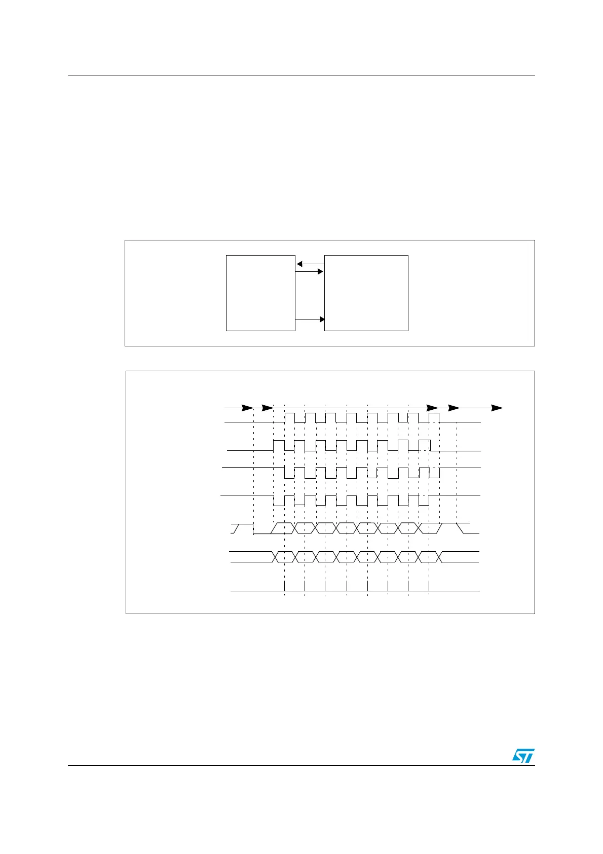
Figure 152. USART example of synchronous transmission
Figure 153. USART data clock timing diagram (M=0)
RX
TX
SCLK
USART
Data out
Data in
Synchronous device
Clock
(e.g. slave SPI)
M=0 (8 data bits)
Clock (CPOL=0, CPHA=1)
Clock (CPOL=1, CPHA=0)
Clock (CPOL=1, CPHA=1)
Start LSB
MSB Stop
* LBCL bit controls last data clock pulse
Start
Idle or preceding
transmission
Data on TX
Stop
Clock (CPOL=0, CPHA=0)
01 23456 7
*
*
*
*
Idle or next
transmission
*
Capture Strobe
LSB
MSB
Data on RX
01 23456 7
(from master)
(from slave)
 Loading...


