UM0306 Analog/digital converter (ADC)
469/519
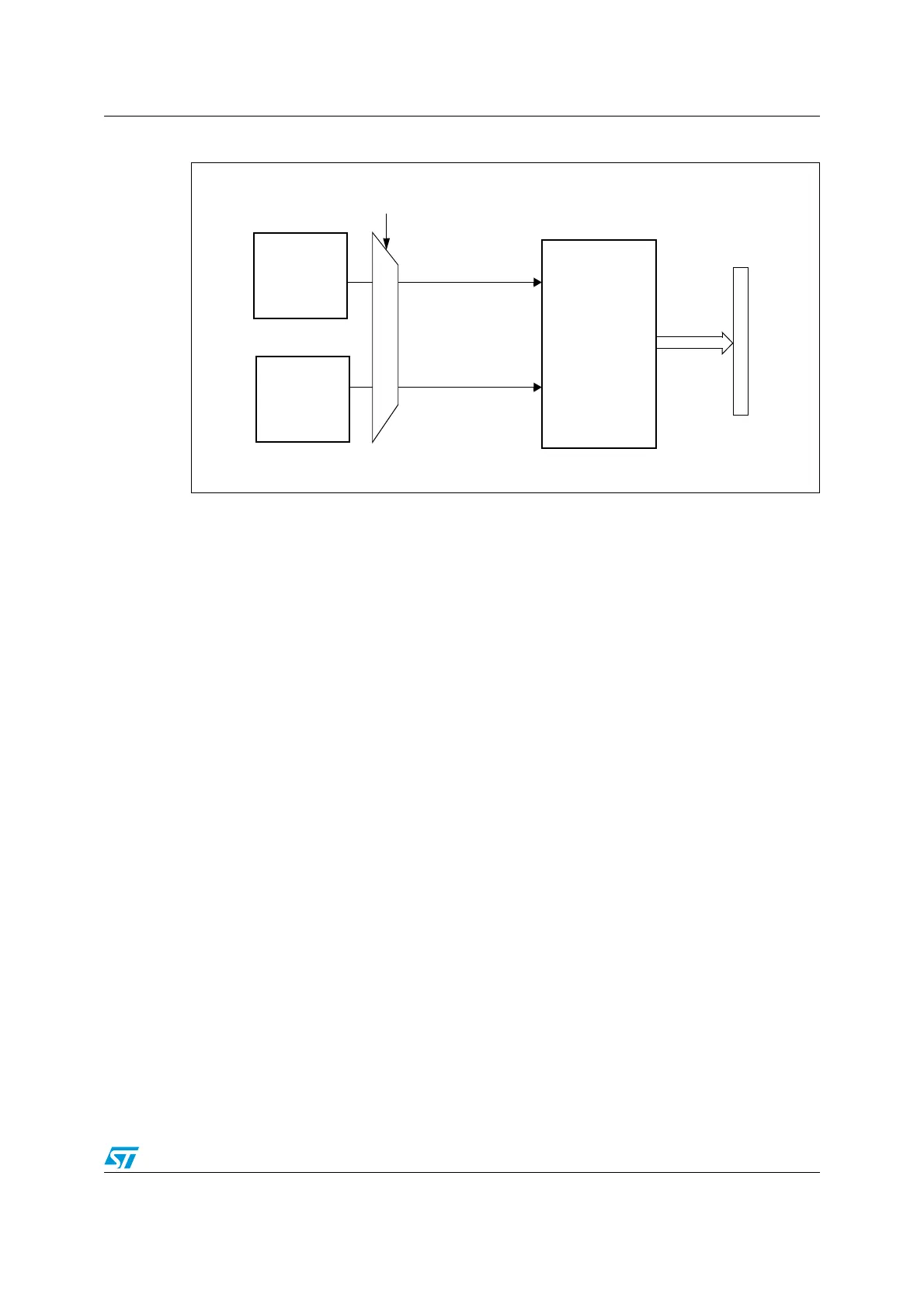
Figure 183. Temperature sensor and V
REFINT
channel block diagram
Reading the temperature
To use the sensor:
4. Select the ADC_IN16 input channel.
5. Select a sample time greater than 2.2 µs
6. Set the TSVREFE bit in the ADC control register 2 (ADC_CR2) to wake-up the
temperature sensor from power down mode.
7. Start the ADC conversion by setting the ADON bit (or by external trigger).
8. Read the resulting V
SENSE
data in the ADC data register
9. Obtain the temperature using the following formula:
Temperature (in °C) = {(V
25
- V
SENSE
) / Avg_Slope} + 25.
Where,
V
25
= V
SENSE
value for 25° C and
Avg_Slope = Average Slope for curve between Temperature vs V
SENSE
(given in
mV/° C or µV/ °C).
Refer to the Electrical characteristics section for the actual values of V
25
and
Avg_Slope.
Note: The sensor has a startup time after waking from power down mode before it can output
V
SENSE
at the correct level. The ADC also has a startup time after power-on, so to minimize
the delay, the ADON and TSVREFE bits should be set at the same time.
19.12 Interrupts
An interrupt can be produced on end of conversion for regular and injected groups and
when the Analog Watchdog status bit is set. Separate interrupt enable bits are available for
flexibility.
SENSOR
TEMPERATURE
V
SENSE
TSVREFE control bit
ADC
Address/data bus
converted data
V
REFINT
ADC_IN16
ADC_IN17
POWER
BLOCK
INTERNAL
 Loading...


