Analog/digital converter (ADC) UM0306
464/519
19.10.1 Injected simultaneous mode
This mode converts an injected channel group. The source of external trigger comes from
the injected group mux of ADC1 (selected by the JEXTSEL[2:0] bits
in the ADC1_CR2
register). A simultaneous trigger is provided to ADC2.
Note: Do not convert the same channel on the two ADCs (no overlapping sampling times for the
two ADCs when converting the same channel).
At the end of conversion event on ADC1 or ADC2:
● The converted data is stored in the ADC_JDRx registers of each ADC interface.
● An JEOC interrupt is generated (if enabled on one of the two ADC interfaces) when the
ADC1/ADC2 injected channels are all converted.
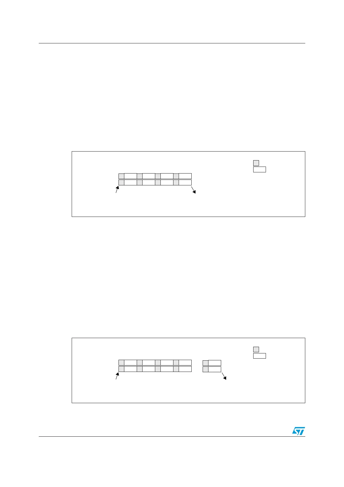
Figure 174. Injected simultaneous mode on 4 channels
19.10.2 Regular simultaneous mode
This mode is performed on a regular channel group. The source of the external trigger
comes from the regular group mux of ADC1 (selected by the EXTSEL[2:0] bits
in the
ADC1_CR2 register). A simultaneous trigger is provided to the ADC2.
Note: Do not convert the same channel on the two ADCs (no overlapping sampling times for the
two ADCs when converting the same channel).
At the end of conversion event on ADC1 or ADC2:
● A 32-bit DMA transfer request is generated (if DMA bit is set) which transfers to SRAM
the ADC1_DR 32-bit register containing the ADC2 converted data in the upper
halfword and the ADC1 converted data in the lower halfword.
● An EOC interrupt is generated (if enabled on one of the two ADC interfaces) when
ADC1/ADC2 regular channels are all converted.
Figure 175. Regular simultaneous mode on 16 channels
CH0 CH1 CH2 CH3
CH3 CH2 CH1 CH0
ADC2
ADC1
Trigger
End of injected conversion on ADC1 and ADC2
Conversion
Sampling
CH0 CH1 CH2 CH3
CH15 CH14 CH13 CH12
ADC1
ADC2
Trigger
End of conversion on ADC1 and ADC2
Conversion
Sampling
CH15
CH0
...
...
 Loading...


