UM0306 Inter-integrated circuit (I2C) interface
339/519
15.4.4 SDA/SCL line control
● If clock stretching is enabled:
– Transmitter mode: If TxE=1 and BTF=1: the interface holds the clock line low
before transmission to wait for the microcontroller to read SR1 and then write the
byte in the Data Register (both buffer and shift register are empty).
– Receiver mode: If RxNE=1 and BTF=1: the interface holds the clock line low after
reception to wait for the microcontroller to read SR1 and then read the byte in the
Data Register (both buffer and shift register are full).
● If clock stretching is disabled in Slave mode:
– Overrun Error in case of RxNE=1 and no read of DR has been done before the
next byte is received. The last received byte is lost.
– Underrun Error in case TxE=1 and no write into DR has been done before the next
byte must be transmitted. The same byte will be sent again.
– Write Collision not managed.
15.4.5 SMBus
Introduction
The System Management Bus (SMBus) is a two-wire interface through which various
devices can communicate with each other and with the rest of the system. It is based on I
2
C
principles of operation. SMBus provides a control bus for system and power management
related tasks. A system may use SMBus to pass messages to and from devices instead of
toggling individual control lines.
The System Management Bus Specification refers to three types of devices. A slave is a
device that is receiving or responding to a command. A master is a device that issues
commands, generates the clocks, and terminates the transfer. A host is a specialized master
that provides the main interface to the system's CPU. A host must be a master-slave and
must support the SMBus host notify protocol. Only one host is allowed in a system.
Similarities between SMBus and I
2
C
● 2 wire bus protocol (1 Clk, 1 Data) + SMBus Alert line optional
● Master-slave communication, Master provides clock
● Multi master capability
● SMBus data format similar to I
2
C 7-bit addressing format (Figure 133).
Differences between SMBus and I
2
C
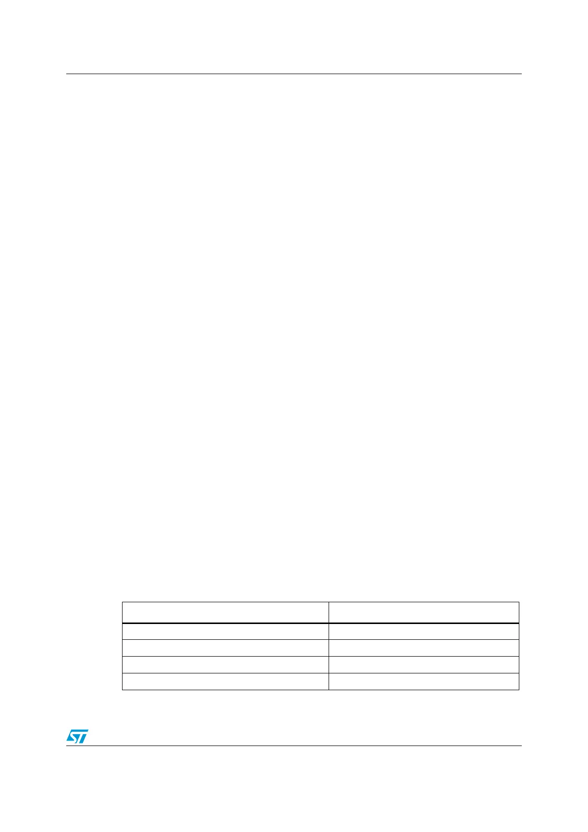
The following table describes the differences between SMBus and I
2
C.
Table 45. SMBus vs I
2
C
SMBus I
2
C
Max. speed 100 kHz Max. speed 400 kHz
Min. clock speed 10 kHz No minimum clock speed
35 ms clock low time-out No time-out
Logic levels are fixed Logic levels are VDD dependent
 Loading...


