General purpose timer (TIMx) UM0306
254/519
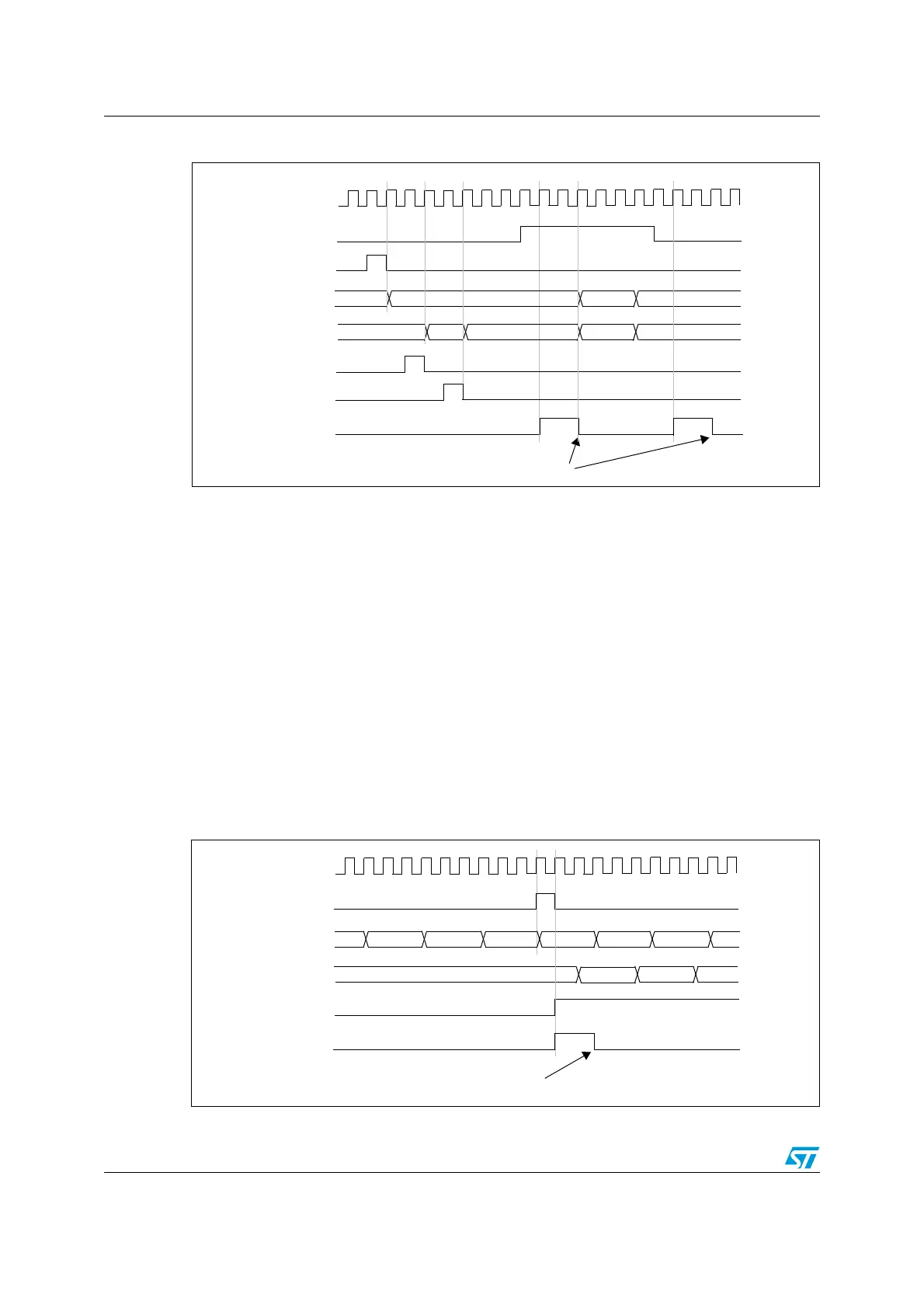
Figure 114. Gating Timer 2 with ENABLE of Timer 1
Using one timer to start another timer
In this example, we set the enable of Timer 2 with the update event of Timer 1. Refer to
Figure 112 for connections. Timer 2 starts counting from its current value (which can be
non-zero) on the divided internal clock as soon as the update event is generated by Timer 1.
When Timer 2 receives the trigger signal its CEN bit is automatically set and the counter
counts until we write ‘0’ to the CEN bit in the TIM2_CR1 register. Both counter clock
frequencies are divided by 3 by the prescaler compared to CK_INT (f
CK_CNT
= f
CK_INT
/3).
● Configure Timer 1 master mode to send its Update Event (UEV) as trigger output
(MMS=010 in the TIM1_CR2 register).
● Configure the Timer 1 period (TIM1_ARR registers).
● Configure Timer 2 to get the input trigger from Timer 1 (TS=001 in the TIM2_SMCR
register).
● Configure Timer 2 in trigger mode (SMS=110 in TIM2_SMCR register).
● Start Timer 1 by writing ‘1’ in the CEN bit (TIM1_CR1 register).
Figure 115. Triggering Timer 2 with UPDATE of Timer 1
TIMER 2-TIF
Write TIF=0
75 00 01
CK_INT
TIMER1-CEN=cnt_en
TIMER1-CNT
TIMER2-CNT
02
TIMER1-cnt_init
AB 00 E7 E8 E9
TIMER2-cnt_init
TIMER2
write CNT
TIMER 2-TIF
Write TIF=0
FD
FE FF
00
01
45 47 48
CK_INT
TIMER1-UEV
TIMER1-CNT
TIMER2-CNT
02
46
TIMER2-CEN=cnt_en
 Loading...


