UM0306 USB full speed device interface (USB)
425/519
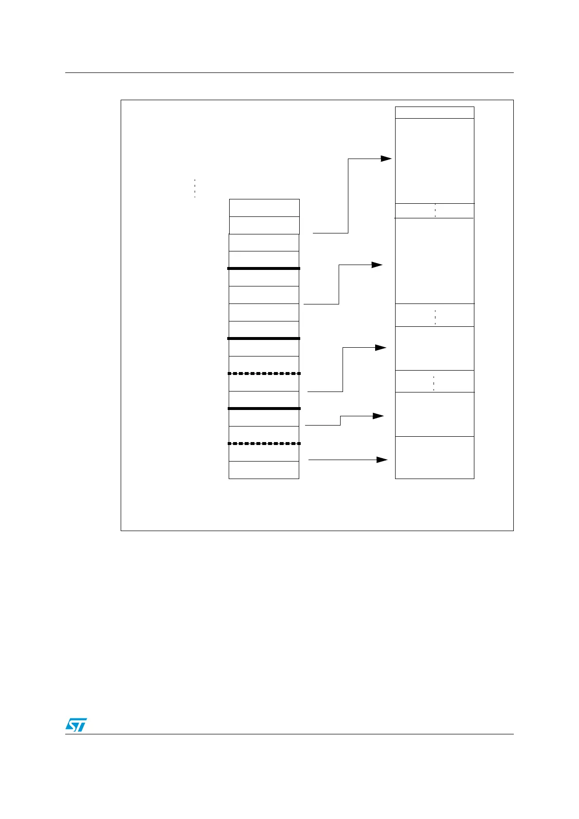
Figure 165. Packet buffer areas with examples of buffer description table locations
Each packet buffer is used either during reception or transmission starting from the bottom.
The USB Peripheral will never change the contents of memory locations adjacent to the
allocated memory buffers; if a packet bigger than the allocated buffer length is received
(buffer overrun condition) the data will be copied to the memory only up to the last available
location.
Buffer for
double-buffered
IN Endpoint 3
ADDR0_TX
COUNT0_TX
0000_0000 (00)
ADDR0_RX
COUNT0_RX
ADDR1_TX
COUNT1_TX
ADDR1_RX
COUNT1_RX
ADDR2_RX_0
COUNT2_RX_0
ADDR2_RX_1
COUNT2_RX_1
ADDR3_TX_0
COUNT3_TX_0
0000_0010 (02)
0000_0100 (04)
0000_0110 (06)
0000_1000 (08)
0000_1010 (0A)
0000_1100 (0C)
0000_1110 (0E)
0001_0000 (10)
0001_0010 (12)
0001_0100 (14)
0001_0110 (16)
0001_1000 (18)
0001_1010 (1A)
Buffer description table locations
Transmission
buffer for
Endpoint 0
Reception buffer
for
Endpoint 0
Transmission
buffer for
single-buffered
Endpoint 1
Packet buffers
ADDR3_TX_1
COUNT3_TX_1
0001_1100 (1C)
0001_1110 (1E)
Buffer for
double-buffered
OUT Endpoint 2
 Loading...


