UM0306 Interrupts and events
103/519
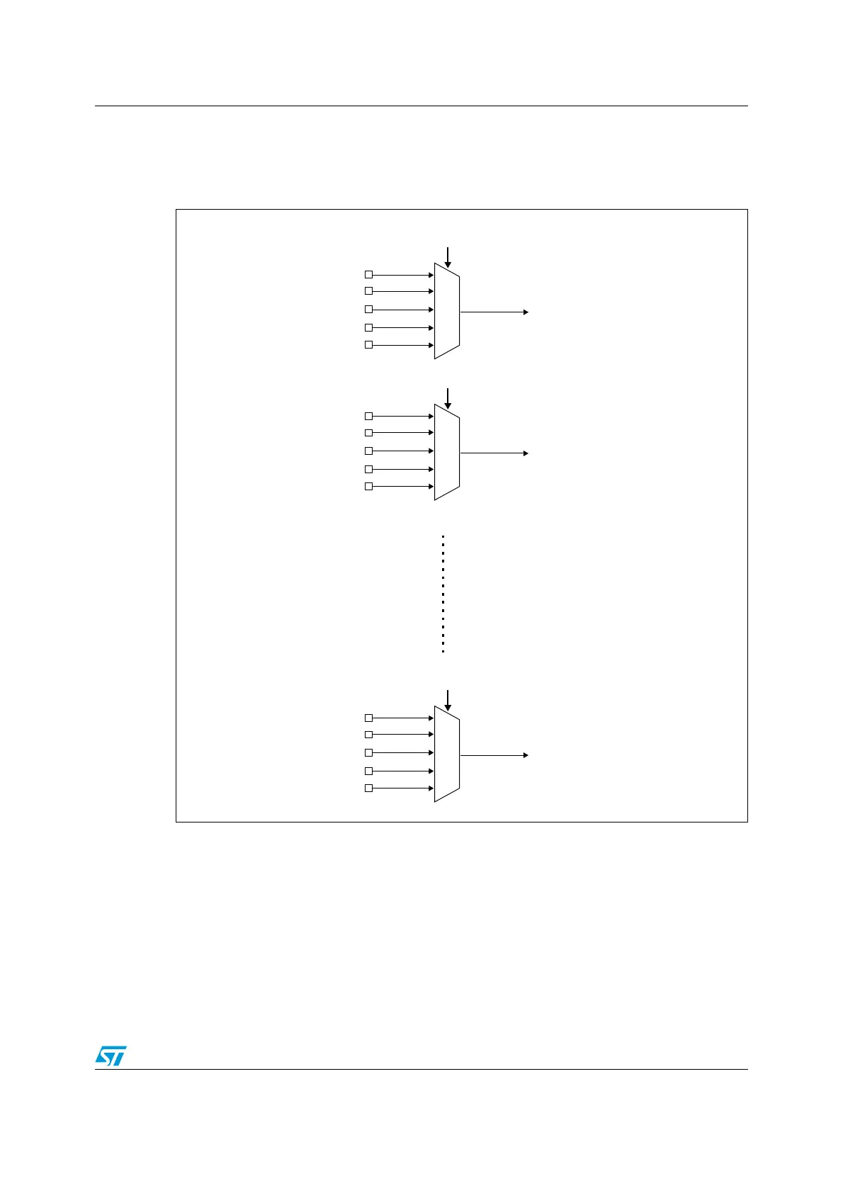
6.2.5 External interrupt/event line mapping
The 80 GPIOs are connected to the 16 external interrupt/event lines in the following manner:
Figure 15. External interrupt/event GPIO mapping
The three other EXTI lines are connected as follows:
● EXTI line 16 is connected to the PVD output
● EXTI line 17 is connected to the RTC Alarm event
● EXTI line 18 is connected to the USB Wake-up event
6.3 EXTI register description
Refer to Section 1.1 on page 23 for a list of abbreviations used in register descriptions.
EXTI0
PA0
PB0
PC0
PD0
PE0
EXTI0[3:0] bits in AFIO_EXTICR1 register
EXTI1
PA1
PB1
PC1
PD1
PE1
EXTI1[3:0] bits in AFIO_EXTICR1 register
EXTI15
PA 15
PB15
PC15
PD15
PE15
EXTI15[3:0] bits in AFIO_EXTICR4 register
 Loading...


