Analog/digital converter (ADC) UM0306
460/519
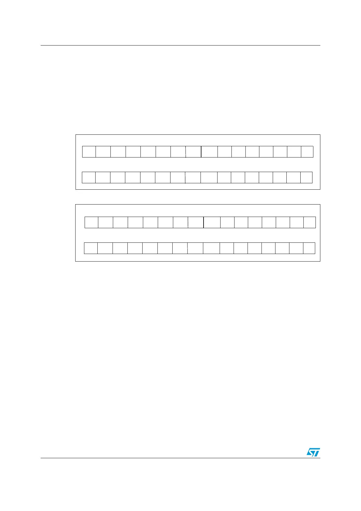
19.6 Data alignment
ALIGN bit in the ADC_CR2 register selects the alignment of data stored after conversion.
Data can be left or right aligned as shown in Figure 171. and Figure 172.
The injected group channels converted data value is decreased by the user-defined offset
written in the ADC_JOFRx registers so the result can be a negative value. The SEXT bit is
the extended sign value.
For regular group channels no offset is subtracted so only twelve bits are significant.
Figure 171. Right alignment of data
Figure 172. Left alignment of data
19.7 Channel-by-channel programmable sample time
ADC samples the input voltage for a number of ADC_CLK cycles which can be modified us-
ing the SMP[2:0] bits in the ADC_SMPR1 and ADC_SMPR2 registers. Each channel can be
sampled with a different sample time.
The total conversion time is calculated as follows:
Tconv = Sampling time + 12.5 cycles
Example:
With an ADCCLK = 14 MHz and a sampling time of 1.5 cycles:
Tconv = 1.5 + 12.5 = 14 cycles = 1µs
19.8 Conversion on external trigger
Conversion can be triggered by an external event (e.g. timer capture, external interrupt). If
the EXTTRIG control bit is set then external event are able to trigger a conversion. The EXT-
SEL[2:0] and JEXTSEL[2:0] control bit allow the application to select decide which out of 8
possible events can trigger conversion for the regular and injected groups.
Note: When an external trigger is selected for ADC regular or injected conversion, only the rising
edge of the signal can start the conversion.
D7D8 D9 D6 D5 D4 D3 D2 D1 D0 D10 D11 SEXT SEXT SEXT SEXT
D7D8 D9 D6 D5 D4 D3 D2 D1 D0 D10 D11
Injected group
Regular group
0000
SEXT D0 D1D11 D10 D9 D8 D7 D6 D5 D2 D3 D4 0 0 0
D0 D1D11 D10 D9 D8 D7 D6 D5 D2 D3 D4 0 0 00
Injected group
Regular group
 Loading...


