UM0306 Analog/digital converter (ADC)
455/519
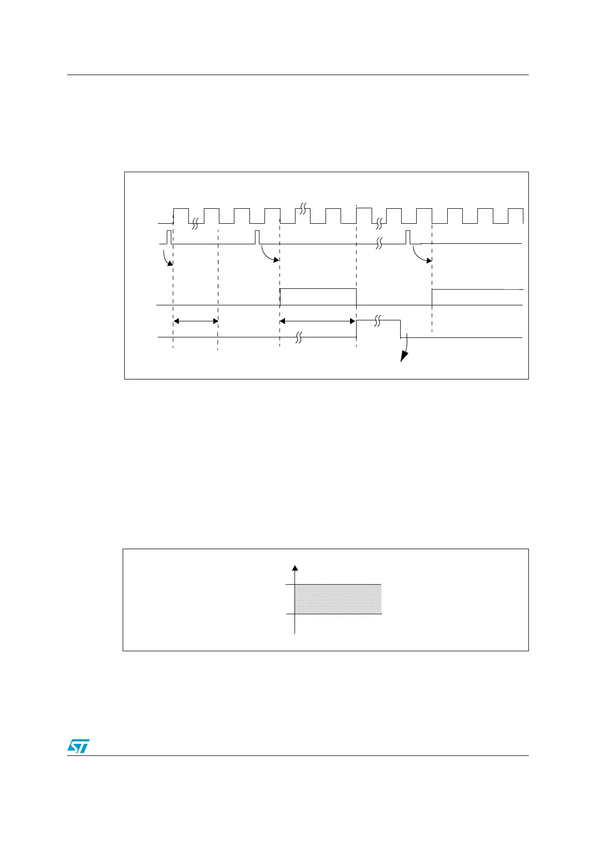
19.4.6 Timing diagram
As shown in Figure 167, the ADC needs a stabilization time of t
STAB
before it starts
converting accurately. After the start of ADC conversion and after 14 clock cycles, the EOC
flag is set and the 16-bit ADC Data register contains the result of the conversion.
Figure 167. Timing diagram
19.4.7 Analog watchdog
The AWD analog watchdog status bit is set if the analog voltage converted by the ADC is
below a low threshold or above a high threshold. These thresholds are programmed in the
12 least significant bits of the ADC_HTR and ADC_LTR 16-bit registers. An interrupt can be
enabled by using the AWDIE bit in the ADC_CR1 register.
The threshold value is independent of the alignment selected by the ALIGN bit in the
ADC_CR2 register. The comparison is done before the alignment (see Section 19.6).
The analog watchdog can be enabled one or more channels by configuring the ADC_CR1
register as shown in Table 66.
Figure 168. Analog watchdog guarded area
ADC_CLK
EOC
Next ADC Conversion
ADC Conversion
Conversion Time
t
STAB
ADC
Software resets EOC bit
SET ADON
ADC power on
(total conv time)
Start 1st conversion
Start next conversion
Analog voltage
High threshold
Low threshold
Guarded area
HTR
LTR
 Loading...


